


E6581528
E-43
5
60Hz default setting (=)
Setting at causes all the following parameters to be set for operation using a base frequency of 60Hz.
(This does not change the settings of any other parameters.)
• Maximum frequency : 60Hz • VI/II input point 2 frequency : 60Hz
• Base frequency 1 : 60Hz • RR/S4 input point 2 frequency : 60Hz
• Base frequency 2 : 60Hz • RX input point 2 frequency : 60Hz
• Base frequency 3 : 60Hz • AI1 input point 2 frequency : 60Hz
• Base frequency 4 : 60Hz • AI2 input point 2 frequency : 60Hz
• Upper limit frequency : 60Hz •
RP/high-speed pulse input point 2 frequency
: 60Hz
• Forward speed limit input level : 60Hz • PID deviation upper limit : 60Hz
• Reverse speed limit input level : 60Hz • PID deviation lower limit : 60Hz
•
Commercial power/inverter switching frequency
: 60Hz • Process upper limit : 60Hz
• Point 2 frequency : 60Hz • PID output upper limit : 60Hz
•
Automatic light-load high-speed operation frequency
: 60Hz •
Motor rated rotational speed
:1680~1775min-1 (According to model)
Default setting (=)
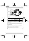
Setting parameter to resets all parameters except the following to their default settings.
When this parameter is set to 3, is displayed for a while, then switches back to the original display
( or ). Note that this setting also clears all trip history records. Trip history data will be cleared at
this time.
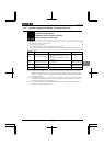
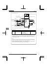
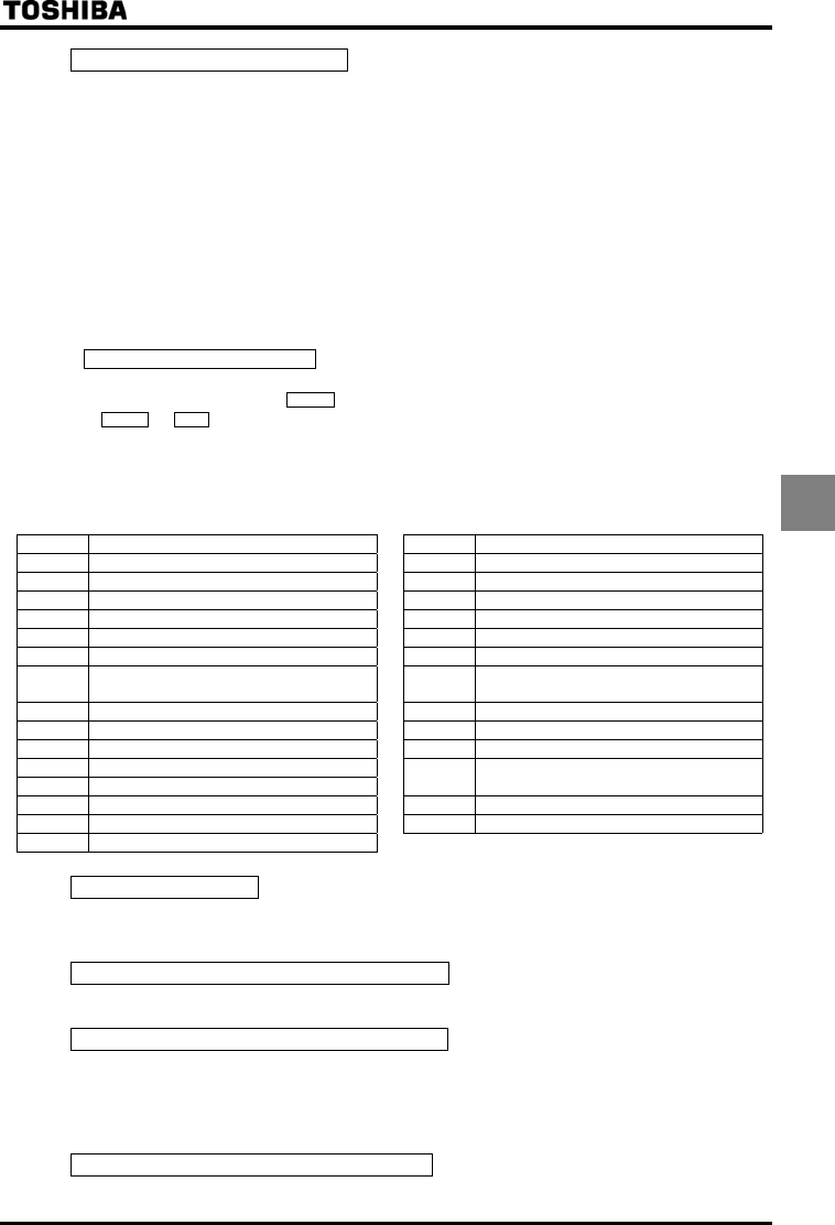
Following parameters are designed considering maintenance that they cannot be reset to the factory default setting
even if you set the parameter at . Following parameters are not displayed on the user parameter group
even if their settings are different from their default settings. So please be careful.
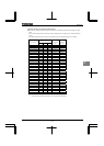
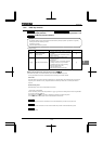
Title Function Title Function
History function Optional AI2 input bias
FM terminal meter selection Optional AI2 input gain
FM terminal meter adjustment
Logic output/pulse train output selection (OUT1)
AM terminal meter selection MON1 terminal meter selection
AM terminal meter adjustment MON1 terminal meter adjustment
Analog VI/VII voltage/current switching MON2 terminal meter selection
Analog AI2 (optional circuit board)
voltage/current switching
MON2 terminal meter adjustment
VI/II input bias FM voltage/current output switching
VI/II input gain MON1 voltage/current output switching
RR/S4 input bias MON2 voltage/current output switching
RR/S4 input gain
RX input bias
~
Quick registration parameter 1~32
RX input gain Free notes
Optional AI1 input bias Network option reset setting
Optional AI1 input gain
Trip clear (=)
Setting to initializes the past four sets of recorded trip history data.
* (The parameter does not change.)
Cumulative operation time clear (=)
Setting to resets the cumulative operation time monitor to the initial value (0 [zero] time).
Initialization of type information (=)
When a trip occurs because of a type error ( is displayed), you can clear the trip by setting to . This
function is used to reformat a control circuit board to adapt it to an inverter, for example, when a circuit board is
removed from an inverter to use another inverter for maintenance or for other reasons. This setting clears all type
data stored in the inverter.
Save user-defined parameters (=)
Setting to causes all the current parameter settings to be stored individually.