


E6581528
J-2
10
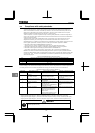
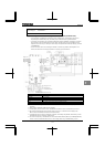
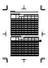
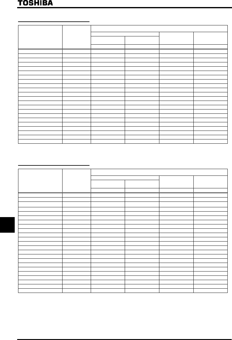
Power supply voltage 600V
Wire size
Main circuit
Input terminal
(R/L1, S/L2, T/L3)
Output terminal
(U/T1, V/T2, W/T2)
DC terminal Earth cable
Inverter model
Applicable
motor
(HP)
AWG AWG AWG AWG
VFAS1-5015PM 2HP 14 14 14 14
VFAS1-5022PM 3HP 14 14 14 14
VFAS1-5040PM 5HP 14 14 10 14
VFAS1-5055PM 7.5HP 12 14 10 14
VFAS1-5075PM 10HP 10 14 8 12
VFAS1-6150PL 15HP 8 8 8 10
VFAS1-6185PL 20HP 8 8 8 10
VFAS1-6220PL 25HP 6 6 6 10
VFAS1-6300PL 30HP 4 4 4 10
VFAS1-6370PL 40HP 3 3 3 8
VFAS1-6450PL 50HP 2 2 2 8
VFAS1-6550PL 60HP 2 2 2 8
VFAS1-6750PL 75HP 1/0 1/0 1/0 6
VFAS1-6900PL 100HP 2/0 2/0 2/0 6
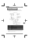
VFAS1-6110KPC
125HP 2/0 2/0 2/0 6
VFAS1-6132KPC
150HP 250MCM 250MCM 250MCM 2
VFAS1-6200KPC
200HP 300MCM 300MCM 300MCM 2
VFAS1-6250KPC
250HP 250MCMx2
250MCMx2
250MCMx2
1
VFAS1-6315KPC
350HP 350MCMx2
350MCMx2
350MCMx2
2/0
VFAS1-6400KPC
450HP 350MCMx3
350MCMx3
350MCMx3
3/0
VFAS1-6500KPC
550HP 300MCMx2x2(*4) 300MCMx4
300MCMx4
4/0
VFAS1-6630KPC
700HP 400MCMx2x2(*4) 400MCMx4
400MCMx4
4/0
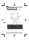
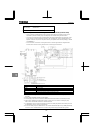
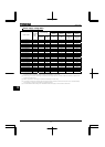
Power supply voltage 690V
Wire size
Main circuit
Input terminal
(R/L1, S/L2, T/L3)
Output terminal
(U/T1, V/T2, W/T2)
DC terminal Earth cable
Inverter model
Applicable
motor
(kW)
mm
2
mm
2
mm
2
mm
2
VFAS1-6022PL 2.2 1.5 1.5 2.5 2.5
VFAS1-6030PL 3 1.5 1.5 2.5 2.5
VFAS1-6055PL 5.5 2.5 1.5 2.5 2.5
VFAS1-6075PL 7.5 2.5 1.5 4 2.5
VFAS1-6110PL 11 4 2.5 4 4
VFAS1-6150PL 15 6 2.5 6 6
VFAS1-6185PL 18.5 10 4 10 10
VFAS1-6220PL 22 10 4 10 10
VFAS1-6300PL 30 10 6 10 10
VFAS1-6370PL 37 16 10 16 16
VFAS1-6450PL 45 25 16 25 16
VFAS1-6550PL 55 35 16 35 16
VFAS1-6750PL 75 50 25 50 25
VFAS1-6900PL 90 70 35 70 35
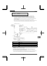
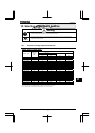
VFAS1-6110KPC
110 70 70 70 35
VFAS1-6132KPC
132 95 70 95 50
VFAS1-6160KPC
160 120
95
120
70
VFAS1-6200KPC
185 185
120
185
95
VFAS1-6250KPC
250 120x2
185
120x2
150
VFAS1-6315KPC
315 150x2
120x2
150x2
150
VFAS1-6400KPC
400 185x2 150x2 150x3 185
VFAS1-6500KPC
500 185x3 150x3 185x3 150x2
VFAS1-6630KPC
630 185x4 185x3 185x4 185x2
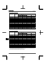
(*1): The recommended cable size is that of the cable (e.g. 1500V class, cupper cable) with continuous maximum permissible temperature of 75°C.
Ambient temperature is 40°C or less and the wiring distance is 30m or less.
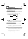
(*2): For the control circuit, use shielded wires whose size (cross-section) is 0.75 mm
2
or more.
(*3): For the earth cable, use wires larger than the specified ones in size (cross-section).
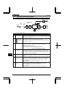
(*4):
The number refers to a cable composition. For example, in the case of “120×2×2”: 120×2×2