


E6581528
E-40
5
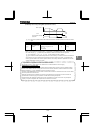
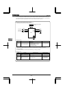
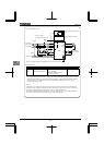
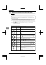
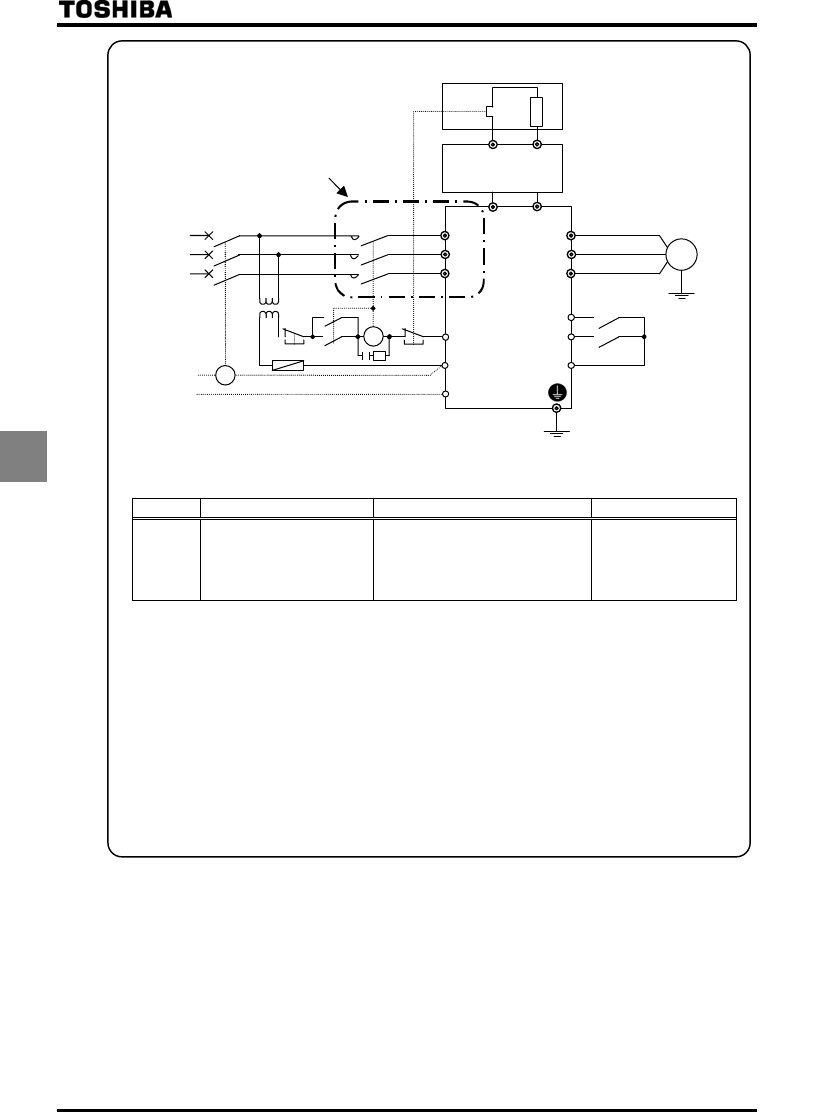
c) VFAS1-6200KPC or more
Fuse
IM
Motor
TC
MC
R/L1
S/L2
T/L3
PA/+
FLB
PC/-
F
FLC
FLA
R
CC
An external braking resistor (optional)
PBR
[Note 1]
MC
MCCB
Three-phase
main circuit
power supply
Power supply
Surge killer
Forward run/stop
Reverse run/stop
* If no power supply is
provided for the control circuit
Inverter
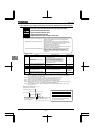
Depression
transformer
200V
TH - Ry
PA
PB
Dynamic braking unit (optional)
PB7
U/T1
V/T2
W/T3
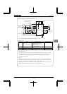
Note 1: Connection when using an MCCB with a top coil instead of an MC.
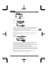
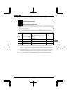
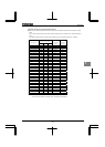
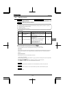
[Parameter setting]
Title Function Adjustment range Example of setting
Dynamic braking selection
:Disabled
:Enabled (braking resistance
overload detect)
:Enabled (braking resistance
overload not detect)
* As a last resort to prevent fire, be sure to connect a thermal relay (THR). Although the inverter has a means of
preventing overload and overcurrent to protect the braking resistor, the thermal relay is activated in case the
protection function fails to work. Select and connect a thermal relay (THR) appropriate to the capacity
(wattage) of the braking resistor.
- Warning -
In the above circuit, the MC in the main circuit is turned off if an inverter's protective function is activated, and
consequently no trip message is displayed. The inverter recovers from a trip if it is turned off. So, check the trip
history record after turning off the inverter and then on again. ⇒ Refer to Section 8.2.1.
To prevent a trip condition from being cleared by turning off the power and then on again, change the setting of
the inverter trip retention selection parameter . ⇒ Refer to Section 6.33.2.