


E6581528
F-57
6
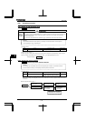
6.33.8 Control mode for low current
: Low current detection hysteresis width
: Low current trip selection
: Low current detection current
: Low current detection time
• Function
If the current is lower than level and passes for a time longer than , the inverter trips.
Trip information is displayed as “.”
=: No tripping (Failure signal FL deactivated).
A low current alarm can be put out by setting the output terminal function selection parameter.
=: The inverter will trip (the failure signal FL will be activated) if a current below the current set with
flows for the period of time specified with .
Title Function Adjustment range Default setting
Low current detection hysteresis width ~ %
Low current trip selection
: No trip
:Trip
Low current detection current ~ %
Low current detection time ~ sec.
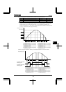
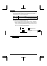
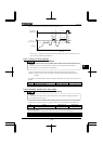
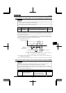
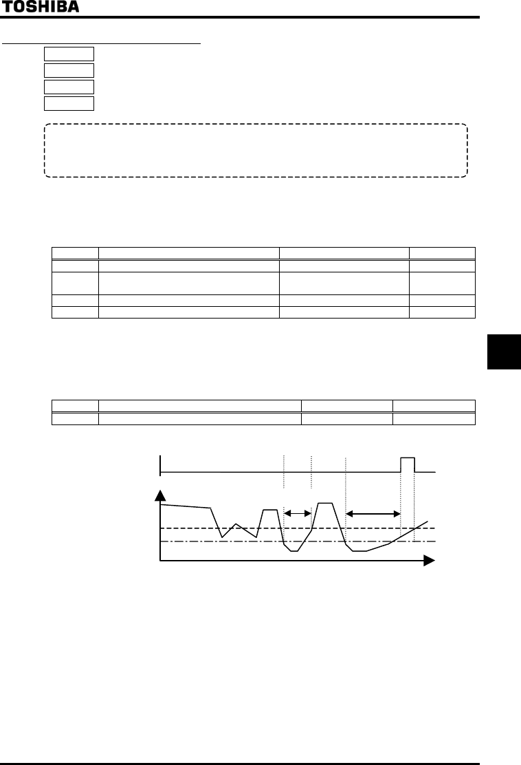
<Example of operation>
Output terminal function: 26 (UC) Low current detection
= (No trip)
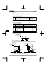
Ex.) When outputting low current detection signals through output terminal OUT1
Title Function Adjustment range Example of setting
Output terminal function selection 1(OUT1) ~
Note: To put out signals to the terminal OUT2, select the parameter .
Time [sec]
+
Output current [%]
Low current
signal output
ON
OFF
OFF
less than
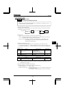
When = (tripping), the inverter will trip if low current lasts for the period of time set with .
After tripping, the low current signal remains ON.