


E6581528
I-5
9
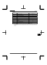
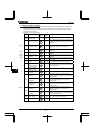
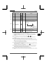
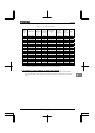
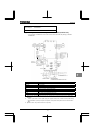
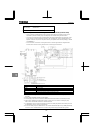
Table 5 AIC, Fuse and Wire sizes
Applicable
motor
(HP)
Inverter model
UL
output current
(A)
*1
AIC (A)
(Interrupting
capacity)
UL-fuse 600V class
and current
(A)
Input wire
sizes of
power circuit
*2
Output wire
sizes of
power circuit
*2
Earth
*2
2
VFAS1-5015PM 2.7 22000 Class J 10A max
AWG14 AWG14 AWG14
3
VFAS1-5022PM 3.9 22000 Class J 10A max
AWG14 AWG14 AWG14
5
VFAS1-5040PM 6.1 22000 Class J 15A max
AWG14 AWG14 AWG14
7.5
VFAS1-5055PM 9.0 22000 Class J 20A max
AWG12 AWG14 AWG14
10
VFAS1-5075PM 11.0 22000 Class J 25A max
AWG10 AWG14 AWG12
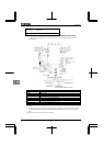
15
VFAS1-6150PL 17.0 22000 Class J 35A max
AWG8 AWG8
AWG
10
20
VFAS1-6185PL 22.0 22000 Class J 45A max AWG8 AWG8
AWG
10
25
VFAS1-6220PL 27.0 22000 Class J 60A max
AWG6 AWG6
AWG
10
30
VFAS1-6300PL 32.0 22000 Class J 60A max
AWG4 AWG4
AWG
10
40
VFAS1-6370PL 41.0 22000 Class J 90A max
AWG3 AWG3
AWG
8
50
VFAS1-6450PL 52.0 22000 Class J 110A max
AWG2 AWG2
AWG
8
60
VFAS1-6550PL 62.0 22000 Class J 125A max
AWG2 AWG2
AWG
8
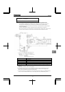
75
VFAS1-6750PL 77.0 22000 Class J 150A max
AWG1/0 AWG1/0
AWG
6
100
VFAS1-6900PL 99.0 22000 Class J 200A max
AWG2/0 AWG2/0
AWG
6
125
VFAS1-6110KPC 125 100000 Class J 200A max
AWG2/0 AWG2/0
AWG
6
150
VFAS1-6132KPC 144 100000 Class J 200A max
AWG3/0 AWG3/0
AWG
2
200
VFAS1-6200KPC 192 100000 Class J 300A max
250MCM 250MCM
AWG
2
250
VFAS1-6250KPC 242 100000 Class J 400A max
2X250MCM 2X250MCM
AWG
1
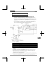
350
VFAS1-6315KPC 336 100000 Class J 500A max
2X350MCM 2X350MCM
AWG
2/0
450
VFAS1-6400KPC 412 100000 Class J 2x300A max
3X300MCM 3X300MCM
AWG
3/0
550
VFAS1-6500KPC 528 100000 Class J 2x400A max
2X(2X300MCM) 4X300MCM
AWG
4/0
700
VFAS1-6630KPC 672 100000 Class J 2x500A max
2X(2X400MCM) 4X400MCM
AWG
4/0
*1: UL output current is different from unit rating output current.
*2: The cables used must be 75°C copper cables within 40°C ambient temperature.
9.2.4 Caution as to the protection of motors from overload
When using the inverter’s thermal protection function to protect the motor from overload, read the instruction
manual included with the inverter carefully and set parameters according to the specifications of the motor used.
When using the inverter to control the operation of multiple motors, install an overload relay for each individual
motor.