


E6581528
M-4
13
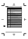
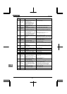
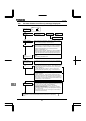
(Continued)
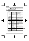
Error
code
Description Possible causes Remedies
Motor constant
setting error
Some items indicated on the motor
nameplate are not entered correctly.
•Base frequency
•Base frequency voltage 1
•Motor rated capacity
•Motor rated current
•Motor rated speed
•Make sure that all items on the motor nameplate
are entered correctly.
Inverter type
error
•Is circuit board (or main
circuit/drive circuit board)
replaced?
•When board has been replaced, input for
.
Analog input
terminal
overvoltage
•Overrated voltage is applied to
analog input.
•Apply voltage within the rated voltage.
Sequence error
•The signal from system is not
inputted into input terminals.
•The input terminal function (,
) is not set up.
•A value other than 0.0 is specified
for , although the brake
answer function is not used.
•Please check if the sequence is normal or not.
•Please set or as the input terminal to
use.
•Please set up 0.0, when you do not use
system-supporting sequence.
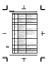
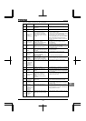
Encoder error
•Disconnection of encoder circuit.
•The encoder is not connected
correctly.
•Check connection of encoder.
Connect encoder correctly.
•Check whether the setting of matches the
phase-A and phase-B connections of the encoder.
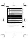
Speed error
(Over speed)
•Encoder error (inverter error) •Check connection of encoder.
Connect encoder correctly.
Key failure
alarm
•The same key is input continuously
more than 20 seconds.
•Check the operation panel.
Terminal input
error
•Braking down of a wire for VI/II
input signal.
•Terminal circuit board comes off
and falls
•P24 overcurrent
•Check VI/II input signal.
•Install the control terminal board to the inverter.
•Check P24 terminal short circuit to CC or CCA.
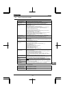
Abnormal
CPU2
communication
•An error arises during CPU2
communication.
•Make a service call.
V/f control error •An internal control error occurs. •Make a service call.
CPU1 fault
•A software error occurs in the
control CPU.
•Make a service call.
Abnormal logic
input voltage
•An abnormal voltage is applied to
the control logic input terminal.
•Check the signal given to the logic connected with
the input terminal.
Option 1 error •Expansion I/O card 1 is defective. •Make a service call.
Option 2 error •Expansion I/O card 2 is defective. •Make a service call.
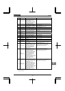
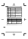
Stop position
retaining error
•A deviation error occurs during
stop position retaining control.
•The stop position adjustment
range specified with is too
narrow.
•Creeping speed is too fast.
•Check connection of encoder.
•Adjust the proportional P gain .
•Increase .
•Lower the creeping speed.
CPU2 fault
•Motor control CPU is defective.
•The drive circuit board in the
inverter was damaged.
•Make a service call.
Control power
backup
undervoltage
error
•The control voltage between +SU
and CC terminals is too low.
•Control power is not supplied
through +SU and CC terminals.
•The parameter is not set
correctly.
•Check whether the voltage between +SU and CC
terminals is DC20V or more.
•Set to 0 if a control power backup device
is not connected to +SU and CC terminals.
To reset the inverter that has been tripped
because of this error, turn it off and then back on.
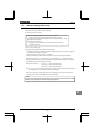
Step-out (for
PM motors
only)
•The motor shaft is locked.
•One output phase is open.
•An impact load is applied.
•Unlock the motor shaft.
•Check the interconnect cables between the
inverter and the motor.
Power removal
error
•Error of power removal signal •Make a service call.
Note: Please contact us if you find any trips other than the above.