


E6581528
F-21
6
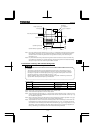
Adjustment with continuous signals (Parameter setting example 1)
Set parameters as follows to adjust the output frequency up or down in proportion to the frequency adjustment signal
input time:
Panel frequency incremental gradient = / setting time
Panel frequency decremental gradient = / setting time
Set parameters as follows to adjust the output frequency up or down almost in synchronization with the adjustment by
the panel frequency command:
= =
( (or ) /)
(/ setting time)
( (or ) /)
(/ setting time)
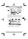
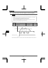
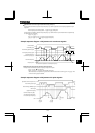
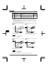
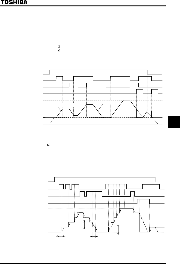
«Sample sequence diagram 1: Adjustment with continuous signals»
The dotted line represents the actual output frequency.
Frequency 0 Hz
Lower limit frequency
Upper limit frequency
Decrementing (DOWN) signal
Incrementing (UP)
RUN command
Set frequency clearing signal
Command frequency [Hz]
Gradient /
Gradient /
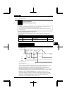
Adjustment with pulse signals (Parameter-setting example 2)
Set parameters as follows to adjust the frequency in steps of one pulse:
,
Pulse ON time
, = Frequency obtained with each pulse
* The inverter does not respond to any pulses with an ON time shorter than set with or . 12ms
or more of clearing signal is allowed.
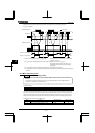
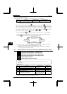
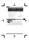
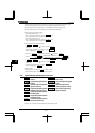
«Sample sequence diagram 2: Adjustment with pulse signals»
Operation command
(
such as F
)
Incrementin
g
(
UP
)
si
g
nal
Decrementin
g
(
DOWN
)
si
g
nal
Clear si
g
nal
Upper limit frequenc
y
0Hz
Command frequency [Hz]
(The dotted line represents
the actual output frequency.)