


E6581528
B-13
2
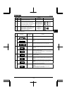
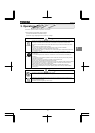
Terminal
symbol
Input/
output
Function (Sink Source logic)
Electrical
specifications
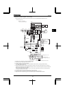
Inverter internal circuits
CCA
*1
Common
to input/
output
Analog input/output signal equipotential (0V)
terminal for the control circuit.
- -
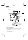
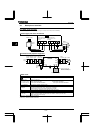
+SU Input
DC power input terminal for operating the
control circuit. Connect a control power backup
device (optional) between +SU and CC.
Voltage:24Vdc±10%
Use a power supply
with a current rating
of 1.05A or more.
FLA
FLB
FLC
Output
Relay contact output. Contact rating
Used to detect the activation of the inverter's
protective function. Contact across FLA-FLC is
closed and FLB-FLC is opened during
protection function operation.
250Vac-2A
30Vdc-1A
:at resistance load
250Vac-1A
:cos
φ=0.4
*1: Although the CC terminal and the CCA terminal are not insulated, they should be used separately, one for the logic circuit and
the other for the analog circuit
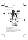
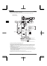
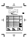
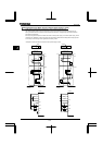
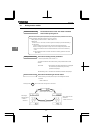
SW SW settings
Default setting
(Settings marked
with ●)
Function
●
Setting for using the inverter’s internal power supply in sink logic
mode
Setting for using the inverter’s external power supply in sink logic
mode
SW1
Setting for operating the inverter in source logic mode
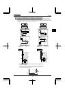
●
Setting for using the analog output terminal FM to output current
of 0-1mA
SW2
Setting for using the analog output terminal FM to output current
of 0-10V or 0-20mA (4-20mA)
0-10V (
=) or 0-20mA (=) can be selected by
changing parameter settings.
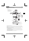
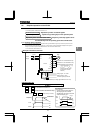
●
Setting for using the input terminal RR/S4 as an analog input
terminal (0-10Vdc)
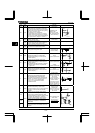
SW3
Setting for using the input terminal RR/S4 as a contact input
terminal
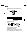
●
Setting for using the output terminal OUT1 as a logic output
terminal
When turning the switch to this position, always set the
parameter
to (logic output).
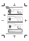
SW4
Setting for using the output terminal OUT1 as a pulse output
terminal
When turning the switch to this position, always set the
parameter
to (pulse output).
P24
FL
FLA
FLB
FLC
P24
1
+SU
CC
SOURCE SINK
PLCINT/PLC INT
SOURCE SINK
PLCINT/PLC INT
SOURCE SINK
PLCINT/PLC INT
0-10V
0-20mA
0-1m
A
FM
0-10V
0-20mA
0-1mA
FM
S4
RR/S4
RR
S4
RR/S4
RR
PULS LO
OUT1
PULS Lo
OUT1