


K-3
E6581528
11
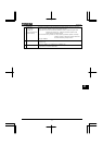
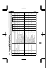
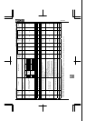
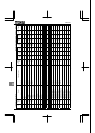
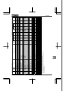
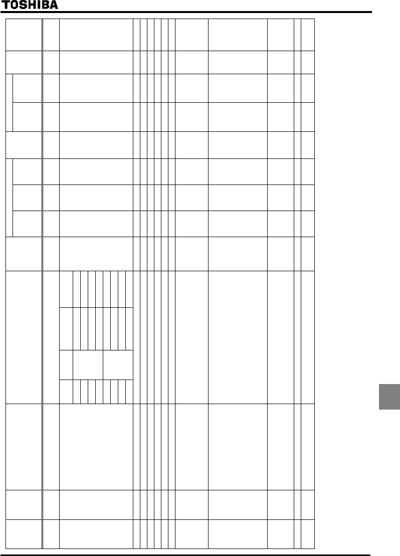
1. Basic parameter [3/4] Sensorless vector/vector with sensor (●:Effective, -:Ineffective)
Default setting Vector control
Title
Communi
cation
No.
Function Adjustment range
Minimum
setting unit
(Panel/Communi
cation)
=
500V
-50Hz
=
575V
-60Hz
=
690V
-50Hz
Write
during
running
Speed
control
Torque
control
V/f
Constant
Reference
0600
Motor electronic thermal
protection level 1
10~100% 1/1 100 100 100 Enabled ●/● ●/● ● 5. 14
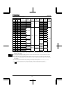
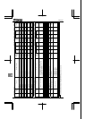
Setting
Motor
type
Overload
protection
OL stall
0 ○ (protect) × (not stall)
1 ○ (protect) ○ (stall)
2 × (not protect) × (not stall)
3
Standard
Motor
× (not protect) ○(stall)
4 ○ (protect) × (not stall)
5 ○ (protect) ○(stall)
6 × (not protect) × (not stall)
0017
Electronic thermal protection
characteristic selection
7
VF Motor
× (not protect) ○(stall)
0 0 0 0 Enabled
●/● ●/● ●
5. 14
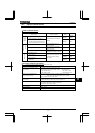
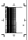
0701 Current/voltage unit selection 0:%, 1:A (ampere)/V (volt) 1/1 0 0 0 Enabled ●/● ●/● ● 5. 15
0005 FM terminal meter selection 0~64 *1 1/1 0 0 0 Enabled ●/● ●/● ● 5. 16
0006 FM terminal meter adjustment - 1/1 *4 *4 *4 Enabled ●/● ●/● ● 5. 16
0670 AM terminal meter selection 0~64 *1 1/1 2 2 2 Enabled ●/● ●/● ● 5. 16
0671 AM terminal meter adjustment - 1/1 *4 *4 *4 Enabled ●/● ●/● ● 5. 16
0300 PWM carrier frequency 2.5~6.0kHz (2.5~4.9kHz) *2 0.1/0.1 *3 *3 *3 Enabled ●/● ●/● ● 5. 17
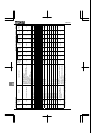
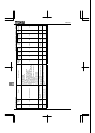
0301 Auto-restart control selection
0:Disabled
1:At auto-restart after momentary stop
2:When turning ST on or off
3:1+2
4:At start-up
1/1 0 0 0 Disabled ●/● ●/● ● 5. 18.1
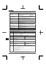
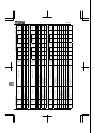
0302
Regenerative power
ride-through control
0:Disabled
1:Power ride-through
2:Deceleration stop during power failure
3:Synchronized deceleration/acceleration
(synchronized acceleration/deceleration
signal)
4:Synchronized deceleration/acceleration
(synchronized acceleration/deceleration
signal+power failure)
1/1 0 0 0 Disabled ●/● -/- ● 5. 18. 2
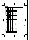
0304 Dynamic braking selection
0:Disabled
1:Enabled (braking resistance overload detect)
2:Enabled (braking resistance overload not
detect)
1/1 0 0 0 Disabled ●/● ●/● ● 5. 19
0308
Dynamic braking
resistance
0.5~1000Ω 0.1/0.1 *3 *3 *3 Disabled ●/● ●/● ● 5. 19
0309
Allowable continuous braking
resistance
0.01~600.0kW 0.01/0.01 *3 *3 *3 Disabled ●/● ●/● ● 5. 19
*1: ⇒ For the adjustment range, see the table on page K-39.
*2: For 37kW and above, the carrier frequency is between 2.5 and 4.9kHz inclusive.
*3: Default values vary depending on the capacity. ⇒ See the table of K-46.
*4: Default setting value is adjusted for connection of frequency meters "QS60T". (Between FM and CCA: Approx. 3.6V) (Between AM and CCA: Approx. 3.6V)