


E6581528
F-68
6
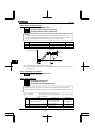
6.35.2 Setting of optional meter outputs
~ , ~ : Meter output settings
⇒ For details, refer to Instruction Manual (E6581341) specified in Section 6.42.
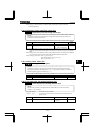
6.35.3 Calibration of analog outputs
: FM voltage/current output switching
, : FM output gradient characteristic and bias adjustment
, : AM output gradient characteristic and bias adjustment
•Function
Output signals from FM/AM terminals are analog voltage signals. Their standard setting range is from 0 to
10Vdc.
The output current from terminal FM can be changed to 0 to 20mAdc (or 4 to 20mAdc) by changing the settings
of terminal SW2 and a parameter.
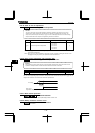
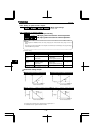
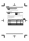
[Parameter setting]
Title Function Adjustment range Default setting
FM voltage/current output
switching
: Voltage 0~10V output
: Current 0~20mA output
FM output gradient
characteristic
: Negative gradient
(descending)
: Positive gradient (ascending)
FM bias adjustment -~. %
AM output gradient
characteristic
: Negative gradient
(descending)
: Positive gradient (ascending)
AM bias adjustment -~. %
Note: To switch to 0-20mAdc (4-20mAdc), set to .
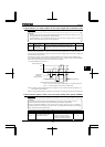
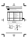
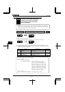
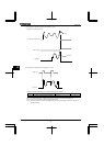
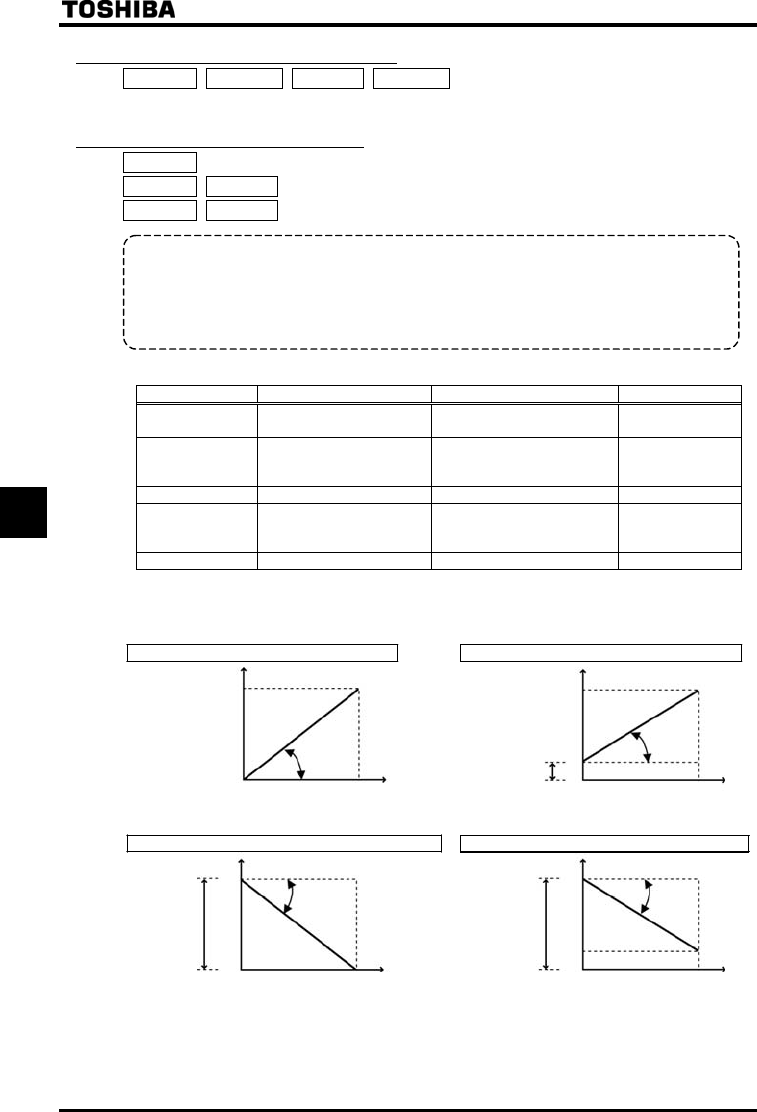
FM terminals setting example
SW2=OFF, = = (%) SW2=OFF, = = (%)
20
0
0
Internal calculated value
100%
0
Internal calculated value
100%
4
Output current
(mA)
20
Output current
(mA)
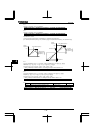
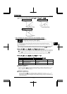
SW2=OFF= = = (%)
SW2=OFF
=
=
=
(%)
20
0
0
Internal calculated value
100%
0 100%
: Large gain
:Small gain
4
Output current
(mA)
20
Output current
(mA)
Internal calculated value
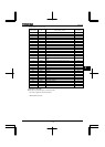
The analog output inclination can be adjusted using the parameter
For code data 50 to 64, negative inclination is invalid.