


E6581528
C-3
3
3.2 Simplified operation of the VF-AS1
On of three operation modes can be selected: terminal board operation, operation panel and combination of both.
⇒ For other operation modes, refer to Section 5.5.
Terminal board mode
:Operation by means of external signals
Operation panel mode :Operation by pressing keys on the operation panel
Operation panel + terminal board mode :Frequency, start/stop signals can be
sent individually from the operating panel and terminal board.
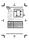
3.2.1 Terminal board operation
In this mode, the motor is started or stopped according to the ON/OFF signal to input terminals (such as the S3
terminal and the F terminal). Also, the frequency is set according to the potentiometer/voltage/current signals to
analog input terminals (such as the RR/S4 terminal, VI/II terminal and RX terminal).
⇒ For more details, refer to Section 7.
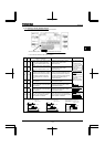
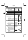
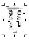
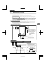
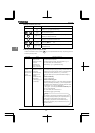
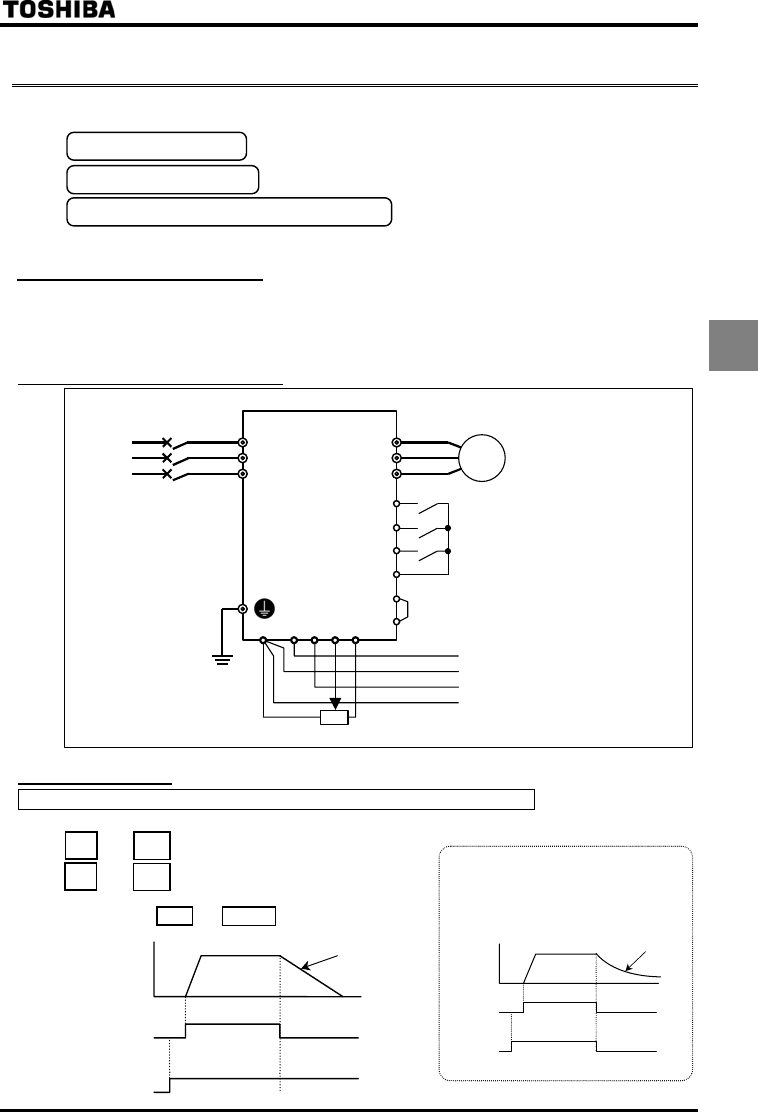
Example of standard connection
Motor
IM
CCA
RX
VI/II
RR/S4
PP
F
R
P24/PLC
R/L1
U/T1
External potentiometer (or voltage signal RR/S4-CCA:0 to 10V)
Volta
g
e si
g
nal:-10~+10Vdc
Voltage signal:0~10Vdc
or current signal:4(0)~20mAdc
ON:Forward run, OFF:Deceleration stop
Stand-by:ON:Stand-by, OFF:Coast stop
(Set the parameters
to
and
to
to
assign the standby signal
input function to the S3
terminal.)
CC
ON:Reverse run, OFF:Deceleration stop
V/T2
W/T3
S/L2
T/L3
Power
supply
MCCB
Inverter
PWR
S3
Run/Deceleration stop
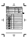
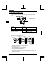
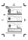
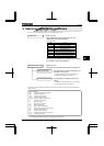
Selecting a command mode for basic parameters
=
(standard default setting)
and are connected: Forward run
and are disconnected: Deceleration stop
(When terminals and are electrically connected)
F
CC
F
CC
P24/PLCPWR
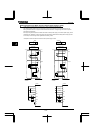
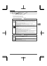
Fre
q
uenc
y
ON
OFF
ON
OFF
F-CC
Deceleration
S3-CC
+
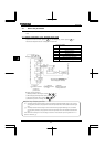
For coast stop
Open the connection between S3 and CC
when stopping the motor in the state
described at left. The monitor on the inverte
r
at this time will display
.
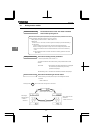
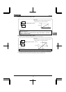
Motor
s
p
eed
ON
OFF
ON
OFF
F-CC
S3-CC
Coast stop