


E6581528
I-8
9
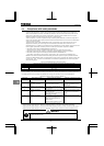
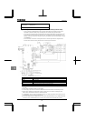
Safety category1: EN954-1 category1, IEC/EN61508, SIL1
Stop category0: IEC/EN60204-1
Coast stop under the control of the MC in the main circuit
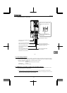
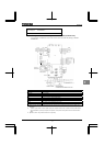
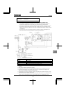
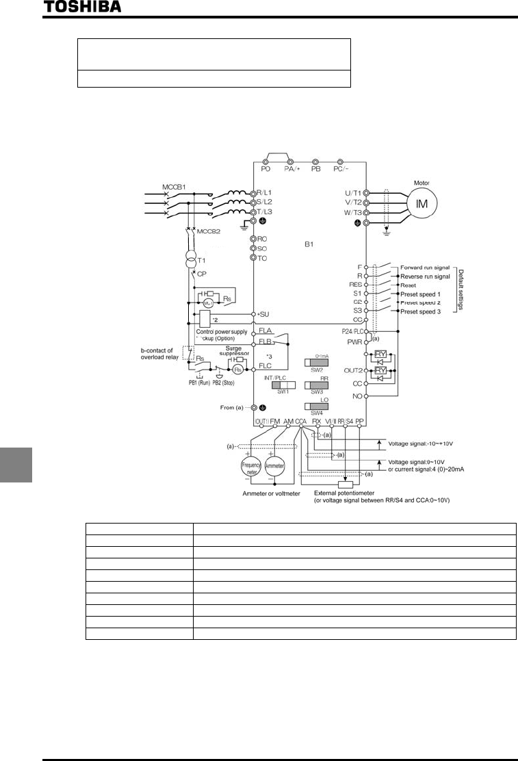
(2) An example of connection for operation in source mode (common: P24)
• In this connection, the PWR terminal is not used. This connection falls under Stop Category 0 defined in
IEC/EN60204-1.
PFL
MC1
down to200V
Transformer
OUT1
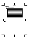
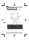
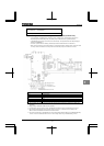
Symbols Description
B1 VF-AS1 inverter
MCCB1 Circuit breaker
MC1 Magnetic contactor
MCCB2 Circuit breaker for control transformer
T1 Control transformer 500,600,690V/200V
CP Circuit protector
PB1 Push button switch (Run)
PB2 Push button switch (Stop/emergency stop)
Rs Control relay
*1: Some inverters* are shipped with the PO and PA/+ terminals short-circuited with a shorting bar. (90kW class
and lower)
*2: To back up the inverter’s internal power supply that supplies control power, an external control power backup
device (CPS002Z - optional) is required. The optional control power backup device can be used with 200V
~
480V.
*3: By default, the FL relay is set as a failure FL output relay.