


E6581528
M-2
13
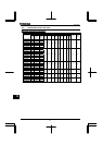
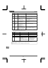
(Continued)
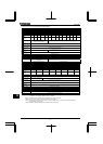
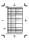
Error
code
Description Possible causes Remedies
Inverter
overload
•Rapid acceleration is operated.
•The DC braking amount is too
large.
•The V/f setting is improper.
•A restart signal is input to the
rotating motor after a momentary
stop, etc.
•The load is too large.
•Increase the acceleration time .
•Reduce the DC braking amount and the
DC braking time .
•Check the V/f parameter setting.
•Use (Auto-restart) and (Regenerative
power ride-though control).
•Use an inverter with a larger rating.
Motor overload
•
The V/f parameter is improperly
set.
•The motor is locked up.
•Low-speed operation is performed
continuously.
•An excessive load is applied to the
motor during operation.
•Check the V/f parameter setting.
•Check the load (operated machine).
•Check the setting and adjust
according to the sustainable overload in the motor
low-speed range.
•Reduce the DC braking amount and the
DC braking time .
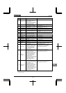
Dynamic
braking resistor
overload
•Rapid deceleration is operated.
•Dynamic braking is too large.
•Increase the deceleration time .
•Increase the capacity of dynamic braking resistor
(wattage) and adjust PBR capacity parameter
.
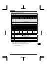
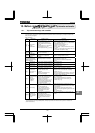
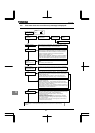
Overvoltage
during
acceleration
•
The input voltage fluctuates abnormally.
(1)The power supply has a capacity
of 500kVA or more.
(2)A power factor improvement
capacitor is opened and closed.
(3)A system using a thyrister is
connected to the same power
distribution line.
•A restart signal is input to the
rotating motor after a momentary
stop, etc.
•Insert a suitable input reactor.
•Use (Auto-restart) and (Regenerative
power ride-though control).
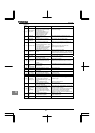
Overvoltage
during
deceleration
•
The deceleration time
is too
short (regenerative energy is too
large).
•The dynamic braking resistor has
a considerably large resistance.
•
(Dynamic braking resistor) is OFF.
Overvoltage limit operation
is OFF.
•
The input voltage fluctuates abnormally.
(1)The power supply has a capacity
of 500kVA or more.
(2)A power factor improvement
capacitor is opened and closed.
(3)A system using a thyrister is
connected to the same power
distribution line.
•Increase the deceleration time .
•Install a dynamic braking resistor.
•Decrease dynamic braking resistance. (Also reset
the .)
•Set dynamic braking mode parameter
properly.
•Set overvoltage limit operation properly.
•Insert a suitable input reactor.
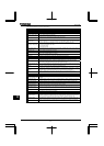
Overvoltage
during fixed
speed operation
•The input voltage fluctuates
abnormally.
(1)The power supply has a capacity
of 500kVA or more.
(2)A power factor improvement
capacitor is opened and closed.
(3)A system using a thyrister is
connected to the same power
distribution line.
•The motor is in a regenerative
state because the load causes the
motor to run at a frequency higher
than the inverter output frequency.
•Insert a suitable input reactor.
•Install a dynamic braking resistor.
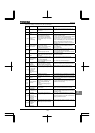
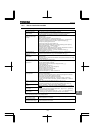
* Overtorque
•Overtorque reaches to a detection
level during operation.
•Stall prevention operation was
performed continuously for a
length of time longer than that set
with .
•Check system error.
•Check whether the motor is overloaded or the
brake is engaged.
*
Low current
operation
•The output current decreased to a
low-current detection level during
operation.
•Check the suitable detection level for the system
().
•Make a service call if the setting is correct.
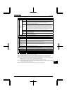
*
Undervoltage
(main circuit)
•The input voltage (in the main
circuit) is too low.
•Momentary power failure occurs
because undervoltage continues
longer than undervoltage detection
time .
•Check the input voltage.
•To cope with a momentary stop due to
undervoltage, enable (Regenerative power
ride-through control), (auto-restart control),
and (Undervoltage detection time).
*Presence or absence of parameter trip can be selected.
(Continued overleaf)