


E6581528
I-4
9
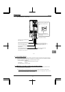
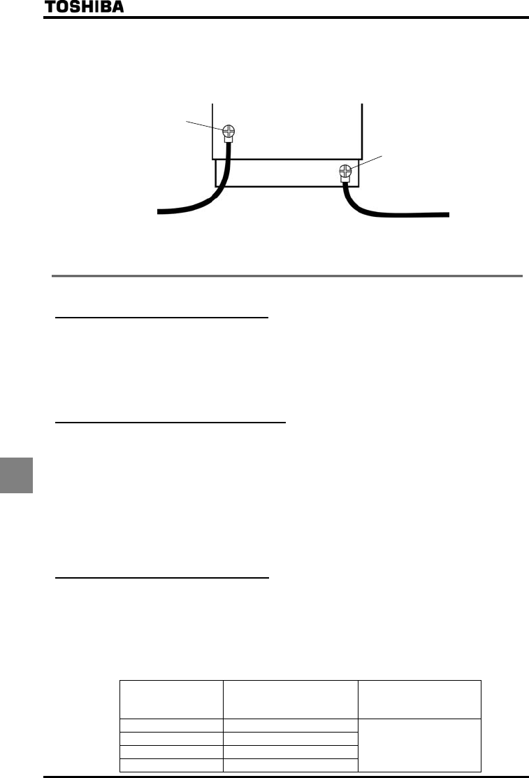
(2) Do not connect two or more wires to the main circuit earth terminal of the inverter. If necessary, install an
additional earth terminal on the EMC plate on which the inverter is installed and connect another cable to it. (Refer
to Fig. 4.) See the table of section 10.1.
(3) Install a non-fuse circuit breaker on the input side of the inverter.
EMC plate
Inverter
Grounding
terminal
Install an earth terminal.
Fig. 4
9.2 Measures to be taken to satisfy the UL/CSA standards
All VF-AS1 series inverters are certified by UL and CSA, and have nameplates with UL and CSA markings.
9.2.1 Caution in installing the inverter
A UL certificate was granted on the assumption that the inverter would be installed in a cabinet. Therefore, install
the inverter in a cabinet and if necessary, take measures to maintain the ambient temperature (temperature in the
cabinet) within the specified temperature range.
For VFAS1-5015PM~5075PM, if the cover on the top of the inverter is removed, the ambient temperature can rise
to 50°C in some cases, although the maximum allowable ambient temperature is 40°C. VFAS1-6022PL~6630KPC
can be used at ambient temperatures of up to 50°C.
9.2.2 Caution in wiring and rated current
For electric wires to be connected to the inverter’s input terminals (R/L1, S/L2, T/L3), output terminals (U/T1, V/T2,
W/T3) or other main circuit terminals, use UL-certified electric wires (copper wires with conductors for which the
maximum allowable temperature is 75°C or over) with ring terminal and tighten the terminal screws (stripped wires
may be connected directly for VFAS1-6022PL~6900PC models) to the specified torque when connecting the wires
to the terminal board.
For FLA, FLB and FLC terminals, the round solderless terminal “V1,25-3” has to be used with UL-certified electric
wire.
To crimp a ring terminal onto a wire, use a crimping tool recommended by the terminal manufacturer.
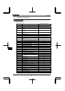
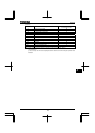
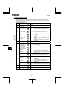
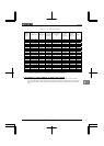
⇒ For recommended electric wire sizes, see Tables 5.
UL-certified rated output current is not the same as inverter unit rated current. Refer to Table 5.
9.2.3 Caution as to peripheral devices
When installing a no-fuse circuit breaker or a fuse box on the primary side of the inverter, use UL-certified one.
The UL certification test on this inverter was conducted under the power supply short-circuit current* conditions
shown in Table 4 (*: current that flows in the event of a short-circuit in the power supply). Note that power supply
short-circuit currents vary depending on the capacity of the motor used.
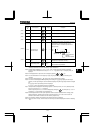
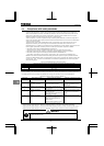
Suitable for use on a circuit capable of delivering not more than following "Power supply short-circuit current (rms)"
symmetrical Amperes,600V max.
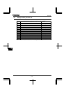
Table 4 Power supply short-circuit current and maximum input voltage
Applicable motor
(kW)
Power supply short-circuit
current (A)
Max. input voltage (V)
1.5~90 22,000
110,132 28000
160~315 35,000
400~630 42,000
600