


E6581528
I-3
9
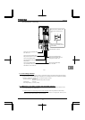
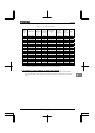
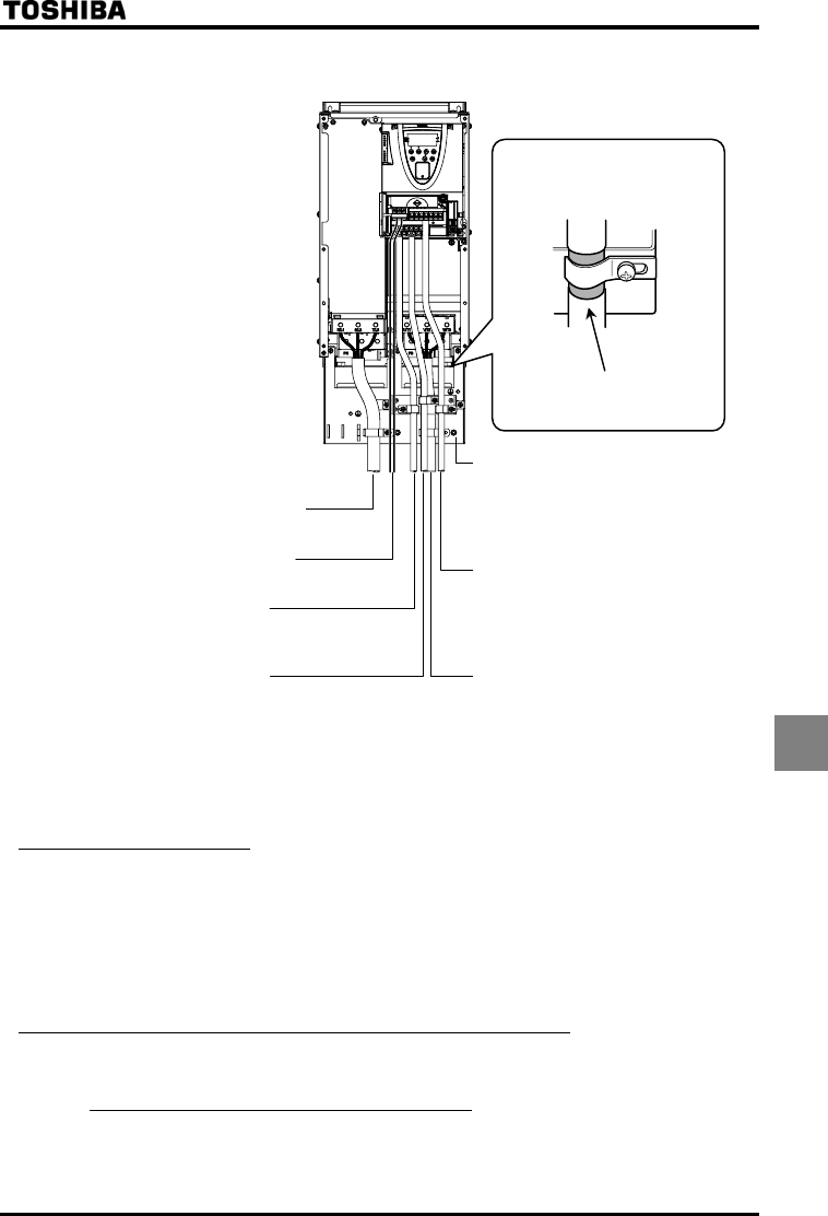
[Ex. Countermeasure - inverter wiring]
Peel off the outer sheath of the
cable and fix the shielded part with
a metal saddle.
Strip and earth the shielded cable,
following the example shown in
Fig.
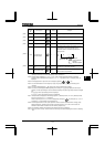
Power supply wiring (Shielded cable)
R/L1, S/L2, T/L3
Control wiring (Shielded cable)
Analog input VI/II, RR/S4, PP, CCA
Analog output FM, AM, CCA
Control wiring (Shielded cable)
Logic input/output +SU, F, R, S1~S3, RES,
NO, P24/PLC, OUT1, OUT2, CC
Motor wiring (Shielded cable)
U/T1, V/T2, W/T3
EMC plate (Refer to Table 2.)
Control wiring (Shielded cable)
The Power Removal safety function input
PWR, P24/PLC
Control wiring (Non-shielded cable)
Relay contact output FLA, FLB, FLC
Fig. 1
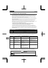
9.1.3 Low-voltage directive
The low-voltage directive provides for the safety of machines and systems. All Toshiba inverters are CE-marked in
accordance with the standard IEC61800-5-1 specified by the low-voltage directive, and can therefore be installed in
machines or systems and imported without a problem to European countries.
Applicable standard: IEC61800-5-1
Adjustable speed electrical power drive system
Pollution level: 2 (4.2.6.2)
Overvoltage category: 3 8.0mm (4.2.6.6)
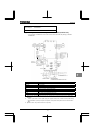
9.1.4 Measures to be taken to satisfy the low-voltage directive
When incorporating the inverter into a machine or system, it is necessary to take the following measures so that
the inverter satisfies the low-voltage directive.
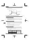
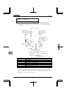
(1) Install the inverter in a cabinet and ground the inverter enclosure.
When doing maintenance, be extremely
careful not to put your fingers into the inverter through a wiring hole and touch a charged part, which may occur
depending on the model and capacity of the inverter used.