


E6581528
F-62
6
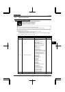
6.33.19 Guide to time of replacement
: Annual average ambient temperature
• Function
You can set the inverter so that it will calculate the remaining useful life of the cooling fan, main circuit
capacitor and on-board capacitor from the ON time of the inverter, the operating time of the motor, the
output current (load factor) and the setting of and that it will display and send out an alarm through
output terminals when each component is approaching the end of its useful life.
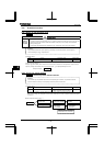
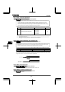
Title Function Adjustment range Default setting
Annual average ambient temperature
: -10~+10°C
: +11~+20°C
: +21~+30°C
: +31~+40°C
: +41~+50°C
: +51~+60°C
Note 1: Using , enter the annual average temperature around the inverter. Be careful not to enter the
annual highest temperature.
Note 2: Set at the time of installation of the inverter, and do not change its setting after the start of use.
Changing the setting may cause a part replacement alarm calculation error.
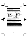
6.33.20 Rush current suppression relay activation time
: Rush current suppression relay activation time
• Function
This parameter is used to control the rush current suppressing resistor shorting relay when a direct current
is passed or multiple inverters are used with their DC sections connected to each other.
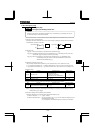
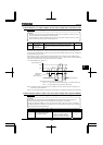
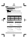
Title Function Adjustment range Default setting
Rush current suppression relay
activation time
~ sec.
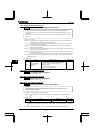
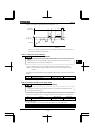
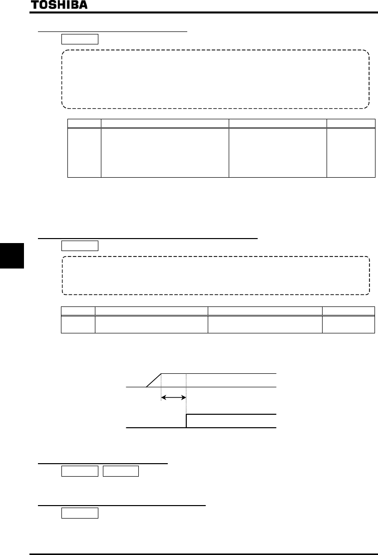
The rush current suppressing relay is activated on the expiration of the time limit set with parameter after the
voltage in the DC section of the inverter has reached the specified level.
DC voltage
ON
Rush current
suppression relay
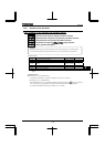
6.33.21 Motor thermal protection
~ : PTC thermal selection
⇒ For details, refer to Instruction Manual (E6581339) specified in Section 6.42.
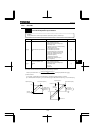
6.33.22 Braking resistance overload curve
: Braking resistance overload time
⇒ Refer to 5.19 for details.