


E6581528
H-7
8
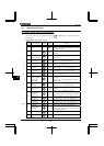
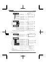
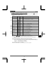
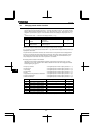
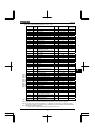
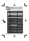
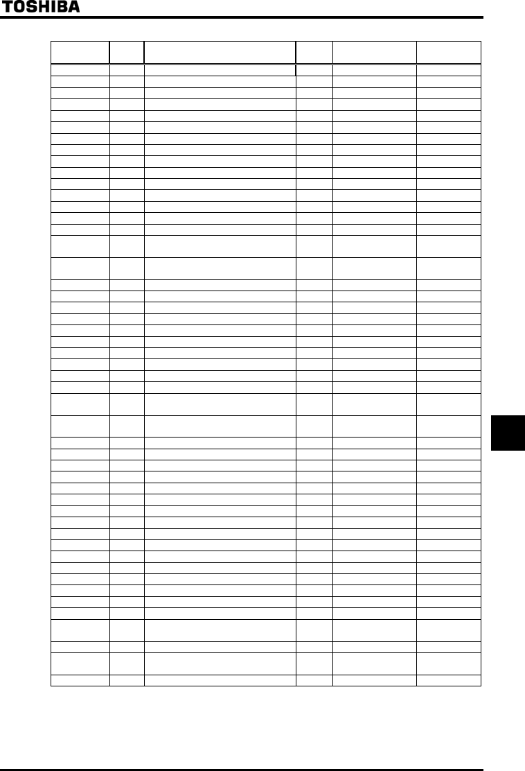
[Setup values of monitor indication parameters (~)]
Communication
No.
Default
setting
Item displayed Marking Unit (Panel)
Unit
(Communication)
FD00 Output frequency Depends on 0.01Hz
FE02 Frequency command value Depends on 0.01Hz
FE03 Output current 1% or 0.01%
FE04 Input voltage (DC detection) 1% or 0.01%
FE05 Output voltage 1% or 0.01%
FE15 Compensated frequency Depends on 0.01Hz
FE16 Speed feedback (real-time value) Depends on 0.01Hz
FE17 Speed feedback (1-second filter) Depends on 0.01Hz
FE18 Torque 1% 0.01%
FE19 Torque command 1% 0.01%
FE20 Torque current 1% 0.01%
FE21 Exciting current 1% 0.01%
FE22 PID feedback value Depends on 0.01Hz
FE23 Motor overload factor (OL2 data) 1% 0.01%
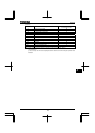
FE24 Inverter overload factor (OL1 data) 1% 0.01%
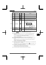
FE25
Regenerative braking resistance
overload factor (OLr data)
1% 1%
FE28
Regenerative braking resistance load
factor (% ED)
1% 1%
FE29 Input power k 0.1kW 0.01kW
FE30 Output power 0.1kW 0.01kW
FE39 Optional AI2 input 1% *2
FE35 RR/S4 input 1% *1
FE36 VI/II input 1% *1
FE37 RX input 1% *1
FE38 Optional AI1 input 1% *2
FE40 FM output 1 1
FE41 AM output 1 1
(FA65) Communication data output [Note 4] [Note 4] [Note 4]
FE66
Attached to expansion I/O card 1 CPU
version
- -
FE67
Attached to expansion I/O card 2 CPU
version
- -
FE76 Integral input power k 0.01(1kWhr) 0.01kWhr
FE77 Integral output power 0.01(1kWhr) 0.01kWhr
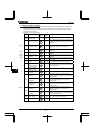
FE00 Signed output frequency Depends on 0.01Hz
FE02 Signed frequency command value Depends on 0.01Hz
FE15 Signed compensated frequency Depends on 0.01Hz
FE16
Signed speed feedback (real-time value)
Depends on 0.01Hz
FE17
Signed speed feedback (1-second filter)
Depends on 0.01Hz
FE18 Signed torque 1% 0.01%
FE19 Signed torque command 1% 0.01%
FE20 Signed torque current 1% 0.01%
FE22 Signed PID feedback value Depends on 0.01Hz
FE37 Signed RX input 1% *1
FE38 Signed optional AI2 input 1% *2
FD50
Light-load high-speed load torque monitor 1
1% 0.01%
FD51
Light-load high-speed load torque monitor 2
1% 0.01%
FE31 Pattern operation group number 0.1 0.1
FE32
Remaining no. of cycles for which
pattern operation is continued
1 1
FE33
Pattern operation preset speed numbers
1 1
FE34
Remaining time for which pattern
operation is continued
0.1 0.1
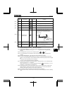
FE71 Rated voltage 0.1v 0.1v
Note 1: *1: Analog value entered: Analog value entered x value monitored/2047
*2: Analog value entered: Analog value entered x value monitored/1023
Note 2: If any value other than the values in the above table is specified, the number “” is displayed.
Note 3: If a negative value is specified, the negative sign “-” is displayed.
The negative sign “-” is affixed only to values
displayed on the monitor. Keep in mind that no sign is affixed to any values read through a communications device.
Note 4: Data set with FA65-FA79 is displayed.
⇒ For details, refer to Instruction Manual (E6581315) specified in Section 6.42.
[Note 3]
[Note 3]
[Note 3]
[Note 3]
[Note 3]
[Note 3]
[Note 3]
[Note 3]
[Note 3]
[Note 3]
[Note 3]