


E6581528
F-10
6
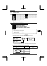
Setting of switching terminals
The V/f1, V/f2, V/f3 and V/f4 switching function is not yet assigned to any terminal. Therefore, it is necessary to
assign them to unused terminals.
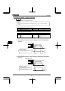
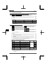
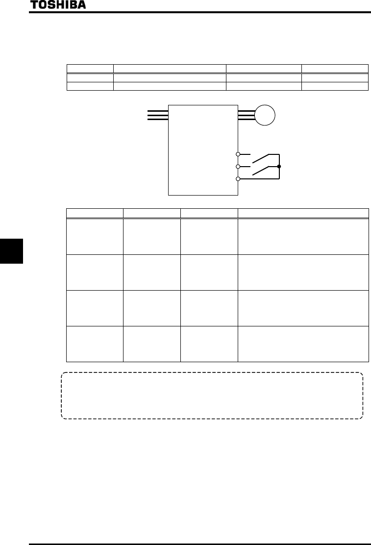
Ex.) Assigning the V/f switching 1 function to S1 and the V/f switching 2 function to S2.
Title Function Adjustment range Example of setting
Input terminal function selection 5 (S1) ~ (V/f switching 1)
Input terminal function selection 6 (S2) ~ (V/f switching 2)
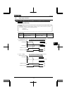
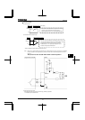
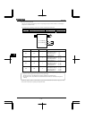
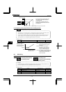
S1: V/f switching 1
S2: V/f switching 2
CC
M
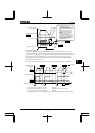
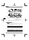
S1-CC S2-CC V/f Parameters selected
OFF OFF 1
Base frequency 1 :
Base frequency voltage 1 :
Manual torque boost 1 :
Thermal protection 1 :
ON OFF 2
Base frequency 2 :
Base frequency voltage 2 :
Manual torque boost 2 :
Thermal protection 2 :
OFF ON 3
Base frequency 3 :
Base frequency voltage 3 :
Manual torque boost 3 :
Thermal protection 3 :
ON ON 4
Base frequency 4 :
Base frequency voltage 4 :
Manual torque boost 4 :
Thermal protection 4 :
+
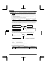
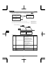
Select V/f1 when using the vector control and the V/f-5 point setting.
Selecting V/f2,.V/f3, or V/f4 disables vector control but enables the V/f constant control.
+
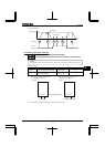
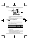
By using “My function,” torque limits and acceleration/deceleration modes can be switched along with V/f
switching.
Note: With the operation panel or communication, the panel acceleration/deceleration selection () can be set.
* This function is active only in operation panel operation mode.