


E6581528
G-1
7
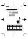
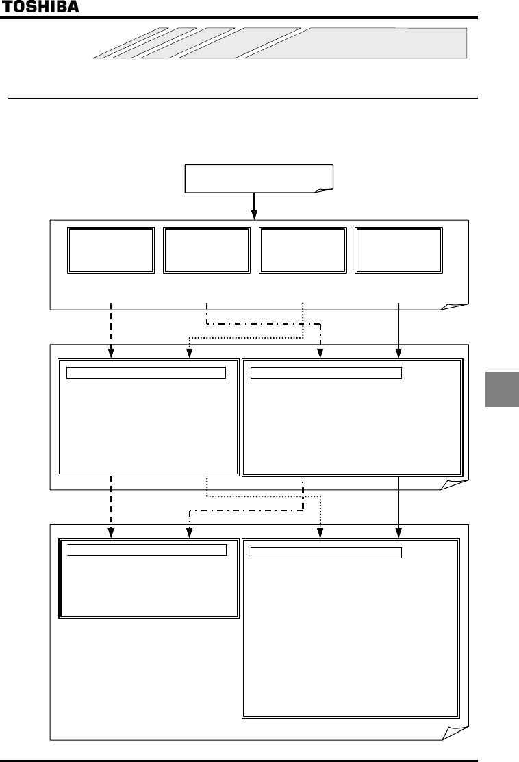
7. Operation with external signal
7.1 External operation
The inverter can be freely controlled externally.
Parameters must be differently set depending on the operation method. Make sure of the operation method before
setting parameters, and set parameters properly to the operation mode according to the procedure mentioned below.
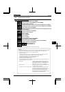
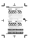
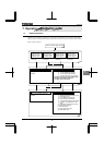
[Steps in setting parameters]
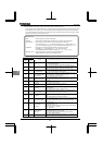
Check of external si
g
nal conditions
In case of control panel operation command input
=
(Operation panel input
enabled)
In case of run/stop with external input
=
(VI/II (voltage/current input))
(RR/S4 (potentiometer/voltage input))
(RX (voltage input))
(2-wire RS485 input enabled)
(4-wire RS485 input enabled)
(Communication option input enabled)
(Optional AI1 (Differential current
input))
(Optional AI2 (voltage/current input))
(UP/DOWN frequency)
(RP pulse input)
(High speed pulse input)
(Binary/BCD input)
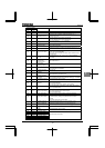
Operation signal:
operation panel
Speed command:
o
p
eration
p
anel
Refer to Section 5.5
Example 1.
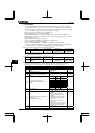
Operation signal:
terminal board
Speed command:
o
p
eration
p
anel
Operation signal:
operation panel
Speed command:
terminal board
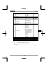
Operation signal:
terminal board
Speed command:
terminal board
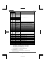
In case of run/stop with external input
=
(Terminal input enabled) *
(2-wire RS485 input enabled)
(4-wire RS485 input enabled)
(Communication option input enabled)
*Sink logic and source logic (logic of input/output
terminal) are switchable to each other.
For details, refer to Section 2.3.2
.
In case of control panel operation command input
=
(Operation panel input
enabled)
Refer to Section 5.5
Example 2.
Refer to Section 5.5
Example 3.
Refer to Section 5.5
Example 4.