E6581528
I-12
9
Safety category3: EN954-1 category3, IEC/EN61508, SIL2
Stop category1: IEC/EN60204-1
Deceleration stop under the control of PWR
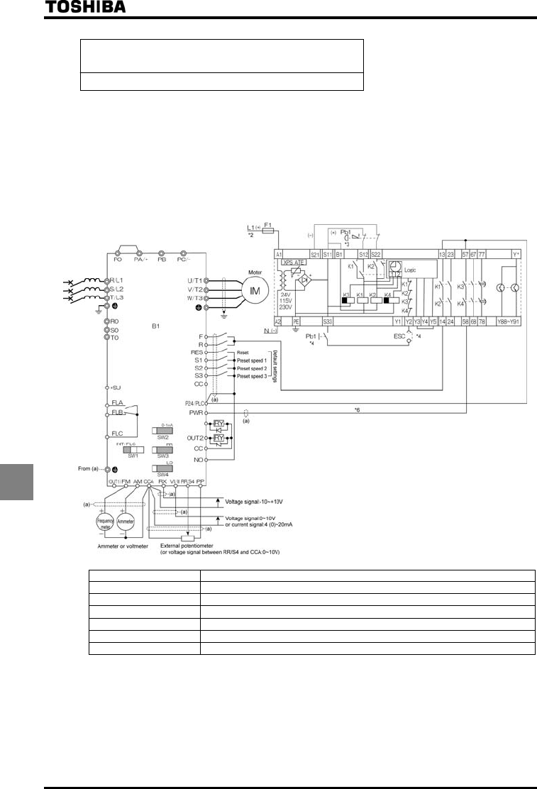
(2) An example of connection for operation in source mode (common: P24)
• In this connection, the PWR terminal is used to connect a safety device. The emergency stop circuit is
supervised by the external safety relay. This safety relay can be shared among several inverters.
• In the event of an emergency stop, the external safety relay issues a deceleration command to the inverter.
At this command, the motor slows down and stops. Then, the safety relay turns off the PWR terminal on
expiration of the time limit (max. 30 sec) set for the relay. This operation falls under Stop Category 1 defined
in IEC/EN60204-1.
• For this connection, the function of issuing the forward run command (2) needs to be assigned to the F
terminal, and the function of issuing the reverse run command (4) to the R terminal.
PFL
MCCB1
OUT1
Symbols Description
B1 VF-AS1 inverter
MCCB1 Circuit breaker
B2 Safety relay: XPS-ATE (manufactured by Schneider Electric)
F1 Fuse
Pb1 Push button switch 2b contact (for emergency stop)
Pb2 Push button switch (for reset and start)
*1: Some inverters* are shipped with the PO and PA/+ terminals short-circuited with a shorting bar. (90kW class
and lower)
*2: Supply voltage: AC/DC24V, AC48V, AC115V, AC230V
*3: If an emergency stop command is issued, the PWR terminal will be turned off to coast and stop the motor.
*4: Pb2 is used to reset/start the inverter after the power is turned on or in the event of an emergency stop.
ESC is used to set reset/start conditions for the external device.
*5: If a deceleration time of more than 30 seconds is required, use a safety relay XPS-AV, which allows you to set
the deceleration time at a maximum of 300 seconds.
*6: To connect a safety relay to the PWR terminal, use a coaxial cable RG174/U (MIL-C17) or KX3B (NFC93-550)
2.54 mm or more in outside diameter and 2 m or less in length. When using a shielded cable, ground it.


