


E6581528
E-18
5
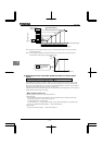
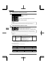
5.11 Setting frequency command characteristics
~
, : VI/II point setting
~
, : RR/S4 point setting
~ : RX point setting
~ :
~ :
~ :
~ : Point 1, 2 setting/ frequency
⇒ For details, refer to Section 7.3.
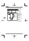
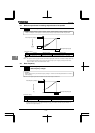
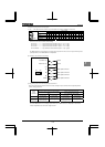
5.12 Preset speed operation (speeds in 15 steps)
~
: Preset speed operation frequencies 1~7
~ : Preset speed operation frequencies 8~15
~ : Preset speed operation frequencies 1~15 operation mode
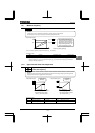
[Setting methods]
1) Run/stop
Run and stop control is experienced by the operation panel (Default setting).
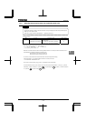
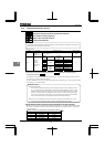
Title Function Adjustment range
Example of setting
Command mode
selection
: Terminal input enabled
: Operation panel input enabled (including
LED/LCD option input)
: 2-wire RS485 communication input
: 4-wire RS485 communication input
: Communication option input
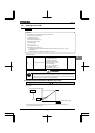
Note 1: If speed commands (analog signal or digital input) are switched in line with preset speed operations, select
the terminal board using the frequency setting mode selection 1 .
⇒ Refer to 3) or Section 5.5.
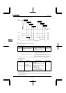
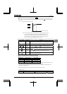
2) Preset speed frequency setting
Set the speed (frequency) of the number of steps necessary.
Setting from speed 1 to speed 7
Title Function Adjustment range Default setting
~
Preset speed operation
frequencies 1~7
~
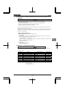
Setting from speed 8 to speed 15
Title Function Adjustment range Default setting
~
Preset speed operation
frequencies 8~15
~
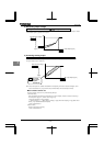
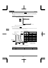
It sets up, when using the optional circuit board.
• Function
A maximum of 15 speed steps can be selected just by switching an external contact signal. Preset speed
frequencies can be programmed anywhere from the lower limit frequency to the upper limit frequency .
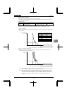
• Function
These parameters adjust the output frequency according to the externally applied analog signal (0~10Vdc
voltage, 4(0)~20mAdc current) and the entered command for setting an external contact frequency.