


E6581528
M-5
13
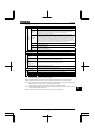
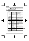
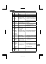
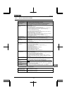
[Alarm] The following are messages only. No trip is developed.
Error
code
Problem Possible causes Remedies
ST signal OFF
•ST terminal (terminal to which the
ST function is assigned) is in
open-circuit.
•Close ST (terminal to which the ST function is
assigned)-CC circuit.
PWR signal
OFF
•PWR terminal is in open-circuit. •Close PWR-P24/PLC circuit.
Control power
backup
undervoltage
•The control voltage between +SU
and CC terminals is too low.
•Control power is not supplied
through +SU and CC terminals.
•The parameter is not set
correctly.
•Check whether the voltage between +SU and CC
terminals is DC20V or more.
•Set to if a control power backup device
is not connected to +SU and CC terminals.
In the event of a error, the inverter will not
be reset automatically even if the control voltage
between +SU and CC terminals returns to its
normal level. To reset the inverter, turn it off and
then back it on.
Undervoltage in
main circuit
•The supply voltage between R, S
and T is under voltage.
•Trouble of rush current restraint
circuit or DC circuit fuse.
•Measure the main circuit supply voltage.
If the voltage is at a normal level, the inverter
requires repairing.
•Make a service call.
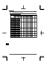
Retry
•The inverter is in the process of
retry.
•A momentary stop occurred.
•The inverter is normal if it restarts after several
tens of seconds. The inverter restarts
automatically. Be careful of the machine because
it may suddenly restart.
Point setting
alarm
•The frequency setting signals at
points 1 and 2 are set too close to
each other.
•Set the frequency setting signals at points 1 and 2
apart from each other.
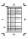
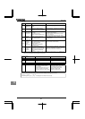
Clear enabling
indication
•This message is displayed when
pressing the STOP key while an
error code is displayed.
•Input terminal RES signal is ON
during trip display.
•Press the STOP key again to clear the trip.
•Turn off the input terminal RES signal.
Emergency stop
enabling
indication
•The operation panel is used to
stop the operation in automatic
control or remote control mode.
•Press the STOP key for an emergency stop. To
cancel the emergency stop, press any other key.
/
Setting error
alarm
An error code
and data are
displayed
alternately twice
each.
•An error is found in a setting when
data is reading or writing.
•Check whether the setting is made correctly.
DC braking
•DC braking in process •The message goes off in several tens of seconds
if no problem occurs. [Note]
Shaft fixing in
control
•Motor shaft fixing control is in
process.
•If the message disappears by stop command (ST
(terminal to which the ST function is assigned)-CC
open), it is normal.
Panel indication
overflow
•The digit number of the item
displayed, e.g., frequency, is in
excess of the specified digit
number.
(Number of overflowing digits is
indicated.)
•For indication of frequency, set multiplying rate
() lower. (Parameter setting that results in
overflow is of course valid.)
Parameters in
the process of
initialization
•Parameters are being initialized to
default values.
•Normal if the message disappears after a while
(several seconds to several tens of seconds).
In auto-tuning 1
•Auto-tuning 1 in process. •Normal if it the message disappears after a few
seconds for 6900PL or less, and 2 or 3 minutes for
6110KPC or larger.
Auto-stop
because of
continuous
operation at the
lower-limit
frequency
•The automatic stop function of
is being performed.
•This function is deactivated when the command
frequency becomes 0.2Hz or more higher than the
lower-limit frequency (LL) or when a command for
stopping operation is entered.
Momentary
power failure
slowdown stop
prohibition
function
activated.
•The deceleration stop function of
(regenerative power
ride-through control) is activated.
•To restart operation, reset the inverter or input an
operation signal again.
(Continued overleaf)