


E6581528
11
K-18
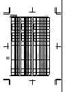
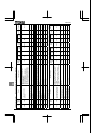
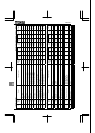
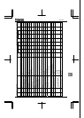
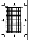
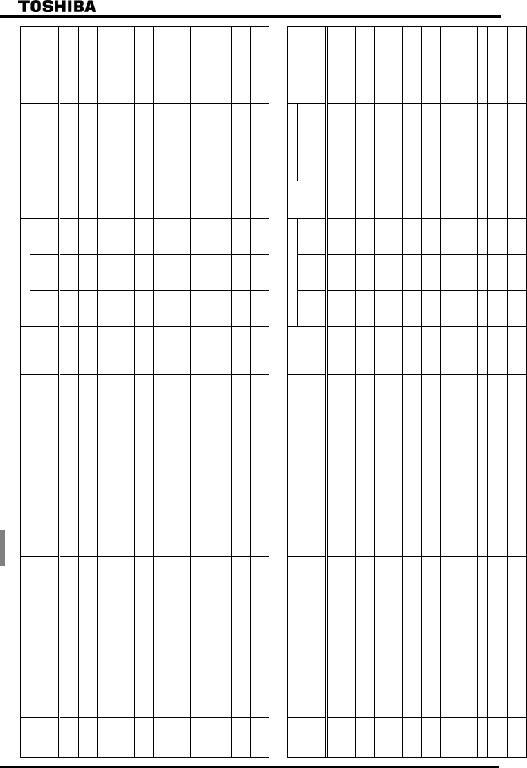
[20] Torque limit [2/2] Sensorless vector/vector with sensor (●:Effective, -:Ineffective)
Default setting
Vector control
Title
Commun
ication
No.
Function Adjustment range
Minimum
setting unit
(Panel/Communi
cation)
=
500V
-50Hz
=
575V
-60Hz
=
690V
-50Hz
Write
during
running
Speed
control
Torque
control
V/f
Constant
Reference
0443
Regenerative braking torque
limit 1 level
0.0~249.9%, 250.0:Disabled 0.1/0.01 250.0 250.0 250.0 Enabled ●/● ●/● - 6. 25. 1
0444
Power running torque limit 2
level
0.0~249.9%, 250.0:Disabled 0.1/0.01 250.0 250.0 250.0 Enabled ●/● ●/● - 6. 25. 1
0445
Regenerative braking torque
limit 2 level
0.0~249.9%, 250.0:Disabled 0.1/0.01 250.0 250.0 250.0 Enabled ●/● ●/● - 6. 25. 1
0446
Power running torque limit 3
level
0.0~249.9%, 250.0:Disabled 0.1/0.01 250.0 250.0 250.0 Enabled ●/● ●/● - 6. 25. 1
0447
Regenerative braking torque
limit 3 level
0.0~249.9%, 250.0:Disabled 0.1/0.01 250.0 250.0 250.0 Enabled ●/● ●/● - 6. 25. 1
0448
Power running torque limit 4
level
0.0~249.9%, 250.0:Disabled 0.1/0.01 250.0 250.0 250.0 Enabled ●/● ●/● - 6. 25. 1
0449
Regenerative braking torque
limit 4 level
0.0~249.9%, 250.0:Disabled 0.1/0.01 250.0 250.0 250.0 Enabled ●/● ●/● - 6. 25. 1
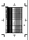
0451
Acceleration/deceleration
operation after torque limit
0:In sync with acceleration/deceleration
1:In sync with min. time
1/1 0 0 0 Disabled ●/● - - 6. 25. 2
0452
Power running stall continuous
trip detection time
0.0~1.0 sec. 0.1/0.1 0.0 0.0 0.0 Enabled ●/● - ● 6. 26. 1
0453
Regenerative braking stall
prevention mode selection
0:Stall during regenerative braking
1:Not stall during regenerative braking
1/1 0 0 0 Enabled ●/● - ● 6. 26. 2
0454
Constant output zone torque
limit selection
0:Constant output limit
1:Constant torque limit
1/1 0 0 0 Disabled ●/● ●/● - 6. 25. 1
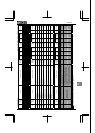
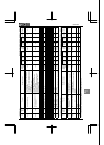
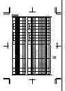
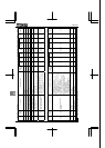
[21] Adjustment parameters [1/2] Sensorless vector/vector with sensor (●:Effective, -:Ineffective)
Default setting
Vector control
Title
Commun
ication
No.
Function Adjustment range
Minimum
setting unit
(Panel/Communi
cation)
=
500V
-50Hz
=
575V
-60Hz
=
690V
-50Hz
Write
during
running
Speed
control
Torque
control
V/f
Constant
Reference
0458
Current control proportional
gain
0~100 1/1 0 0 0 Disabled ●/● ●/● - *1
0460 Speed loop proportional gain 1~9999 1/1 12 12 12 Enabled ●/● - - *1
0461
Speed loop stabilization
coefficient
1~9999 1/1 100 100 100 Enabled ●/● - - *1
0462 Moment of inertia of load 1
0~100 1/1 35 35 35 Enabled ●/● - - *1
0463
Second speed loop proportional
gain
1~9999 1/1 12 12 12 Enabled ●/● - - *1
0464
Second speed loop
stabilization coefficient
1~9999 1/1 100 100 100 Enabled ●/● - - *1
0465 Moment of inertia of load 2 0~100 1/1 35 35 35 Enabled ●/● - - *1
0466 Speed PI switching frequency 0.0~ Hz 1/1 0.0 0.0 0.0 Enabled ●/● - - *1
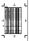
0467 Motor oscillation control
0:Disabled
1:Enabled(Low gain)
2:Enabled(Middle gain)
3:Enabled(High gain)
1/1 0 0 0 Disabled -/- -/- ● 6.27.2
0470 VI/II input bias 0~255 1/1 *2 *2 *2 Enabled ●/● ●/● ● 6. 28
0471 VI/II input gain 0~255 1/1 *2 *2 *2 Enabled ●/● ●/● ● 6. 28
0472 RR/S4 input bias 0~255 1/1 *2 *2 *2 Enabled ●/● ●/● ● 6. 28
0473 RR/S4 input gain 0~255 1/1 *2 *2 *2 Enabled ●/● ●/● ● 6. 28
0474 RX input bias 0~255 1/1 *2 *2 *2 Enabled ●/● ●/● ● 6. 28
*1: ⇒ For details, refer to Instruction Manual (E6581333) specified in Section 6.42. *2: ⇒ Settings vary from unit to unit. Even if is set to , no change is made to these values.