


E6581528
A-20
1
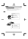
Loads that generate negative torque
When combined with loads that generate negative torque the protection for overvoltage and overcurrent on the
inverter will go into operation and may cause a trip. For this kind of situation, you must install a dynamic braking
resistor, etc. that complies with the load conditions.
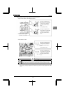
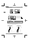
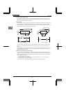
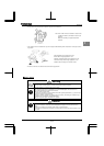
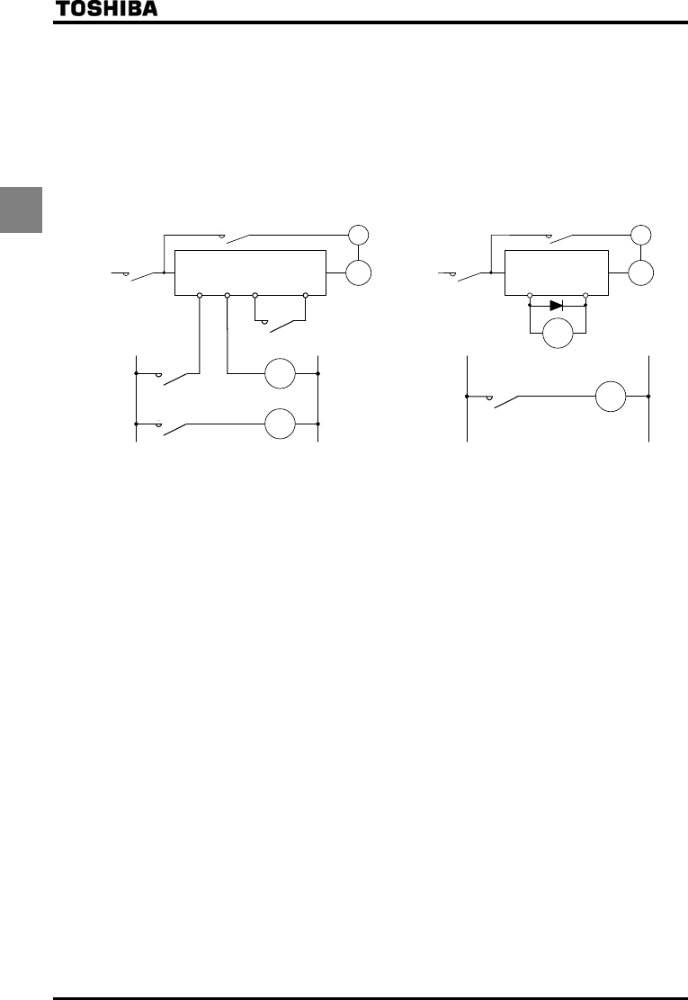
Motor with brake
If a brake motor is used with the braking circuit connected to the output terminals of the inverter, the brake cannot
be released because of a voltage drop at startup. Therefore, when using the inverter along with a brake motor,
connect the braking circuit to the power supply side of the inverter, as shown in the figure below. In most cases, the
use of a brake motor causes an increase in noise at low-speed.
B
IM
LOW
OUT1
P24
Three-
phase
power
supply
MC2
MC3
MC2
MC1
MC2
B
IM
MC3
MC1
MC3
FLB
FLC
PWR
P24
Three-
phase
power
supply
LOW
(Non-exciting brake)
(Non-exciting brake)
MC1
MC2
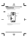
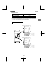
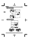
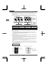
Circuit configuration 1 Circuit configuration 2
In circuit configuration 1, the brake is turned on and off through MC2 and MC3. If the circuit is configured in some
other way, the overcurrent trip may be activated because of the locked rotor current when the brake goes into
operation.
Circuit configuration 2 uses low-speed signal OUT1 to turn on and off the brake. Turning the brake on and off with a
low-speed detection (OUT1 function) may be better in such applications as elevators. Please confer with your
supplier before designing the system.
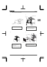
Measures to protect motors against surge voltages
In a system in which a 500/575/690V-class inverter is used to control the operation of a motor, very high surge
voltages may be produced. When applied to the motor coils repeatedly for a long time this can cause deterioration
of their insulation, depending on the wire length, wire routing and types of wires used. Here are some examples of
measures against surge voltages.
(1) Lower the inverter’s carrier frequency.
(2) Set the parameter
(Carrier frequency control mode selection) to or . (Default setting )
(3) Use motors with a high dielectric strength.
(4) Insert an reactor or a surge voltage suppression filter between the inverter and the motor.