


Thermocouple Measurements
To connect a thermocouple to the module’s screw terminals, see page 21.
• The instrument supports the following thermocouple types:
B, E, J, K, N, R, S, and T using
ITS-90 software conversions.
The default is a J-Type thermocouple.
• Thermocouple measurements require a reference junction temperature.
For the reference junction temperature, you can use an internal
measurement on the module, an external thermistor or
RTD
measurement, or a known fixed junction temperature.
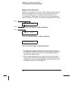
• If you select an external reference, the instrument automatically
reserves channel 01 on the multiplexer in the lowest slot as the
reference channel (thermistor or
RTD measurement). If you have
more than one multiplexer installed, channel 01 on the module in the
lowest slot is used as the reference for the entire instrument.
• Before configuring a thermocouple channel with an external
reference, you must configure the reference channel (channel 01)
for a thermistor or
RTD measurement. An error is generated if you
attempt to select the external reference source before configuring the
reference channel. An error is also generated if you change the
function on the reference channel after selecting the external
reference for a thermocouple channel.
• If you select a fixed reference temperature, specify a value between
-
20
°C and +80 °C (always specify the temperature in °C regardless
of the temperature units currently selected).
• The accuracy of the measurement is highly dependent upon the
thermocouple connections and the type of reference junction used.
Use a fixed temperature reference for the highest accuracy
measurements. The internal isothermal block reference provides
the lowest accuracy measurements. For more information on
reference junction temperature measurements and associated errors,
see the sections on pages 345 and 352.
• The thermocouple check feature allows you to verify that your
thermocouples are properly connected to the screw terminals for
measurements. If you enable this feature, the instrument measures
the channel resistance after each thermocouple measurement to
ensure a proper connection. If an open connection is detected (greater
than 5 k
Ω on the 10 kΩ range), the instrument reports an overload
condition for that channel (or displays “OPEN T/C” on the front panel).
4
Chapter 4 Features and Functions
Temperature Measurement Configuration
107