


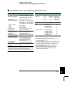
To Calculate Total Measurement Error
Each specification includes correction factors which account for errors
present due to operational limitations of the internal
DMM. This section
explains these errors and shows how to apply them to your measurements.
Refer to “Interpreting Internal
DMM Specifications,” starting on page 416,
to get a better understanding of the terminology used and to help you
interpret the internal
DMM’s specifications.
The internal
DMM’s accuracy specifications are expressed in the form:
(% of reading + % of range). In addition to the reading error and range
error, you may need to add additional errors for certain operating
conditions. Check the list below to make sure you include all measurement
errors for a given function. Also, make sure you apply the conditions as
described in the footnotes on the specification pages.
• If you are operating the internal DMM outside the 23 °C ± 5 °C
temperature range specified, apply an additional temperature
coefficient error.
• For dc voltage, dc current, and resistance measurements, you may
need to apply an additional reading speed error.
• For ac voltage and ac current measurements, you may need to apply
an additional low frequency error or crest factor error.
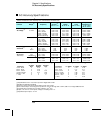
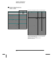
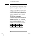
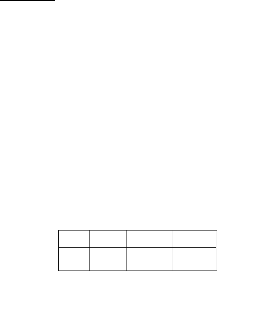
Understanding the “ % of reading ” Error The reading error
compensates for inaccuracies that result from the function and range
you select, as well as the input signal level. The reading error varies
according to the input level on the selected range. This error is
expressed in percent of reading. The following table shows the reading
error applied to the internal
DMM’s 24-hour dc voltage specification.
Range Input Level
Reading Error
(% of reading)
Reading
Error Voltage
10 Vdc
10 Vdc
10 Vdc
10 Vdc
1 Vdc
0.1 Vdc
0.0015
0.0015
0.0015
≤ 150 µV
≤ 15 µV
≤ 1.5 µV
Chapter 9 Specifications
To Calculate Total Measurement Error
414