


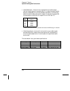
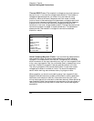
• Cable Resistance – Varies with wire gauge size and cable length.
Use the largest gauge wire possible and try to keep the cable lengths
as short as possible to minimize the cable resistance. The following
table lists typical cable resistance for copper wire of several gauge sizes
(the temperature coefficient for copper wire is 0.35% per
°C).
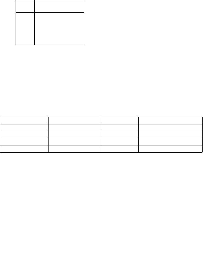
AWG
Ω / ft (2 conductors)
at 25 °C
14
16
18
20 *
22
24
5 m
Ω
10 mΩ
15 mΩ
20 mΩ
30 mΩ
50 mΩ
* Recommended wire size for the screw terminals on 34970A plug-in modules.
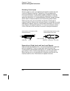
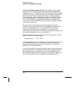
• Cable Capacitance – Varies with the insulation type, cable length,
and cable shielding. Cables should be kept as short as possible to
minimize cable capacitance. In some cases, low-capacitance cable
can be used.
The table below lists typical cable specifications.
Cable Type Nominal Impedance Capacitance Attenuation
Twisted Pair 100
Ω at 1 MHz 10 to 20 pF/ft Up to 1 dB/100 ft at 1 MHz
Shielded Twisted Pair 100
Ω at 1 MHz 10 to 20 pF/ft Up to 1 dB/100 ft at 1 MHz
Coaxial 50
Ω or 75Ω at 100 MHz 15 to 25 pF/ft Up to 6 dB/100 ft at 100 MHz
Twisted Pair Ribbon 100
Ω at 1 MHz 15 to 20 pF/ft Up to 1 dB/100 ft at 1 MHz
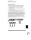
Chapter 8 Tutorial
System Cabling and Connections
336