Snubber Circuits
Whenever a relay contact opens or closes, electrical breakdown or
arching can occur between the contacts. This can cause high-frequency
noise radiation, voltage and current surges, and physical damage to the
relay contacts.
A breadboard area is provided on the 34903A to implement custom
circuitry such as simple filters, snubbers, and voltage dividers.
The breadboard area provides the space necessary to insert your own
components but there are no circuit board traces here. You can build
these networks to provide contact protection when actuating ac power
line for reactive loads. Although many types of contact protection
networks can be used, only
RC networks and varistors are described in
this section.
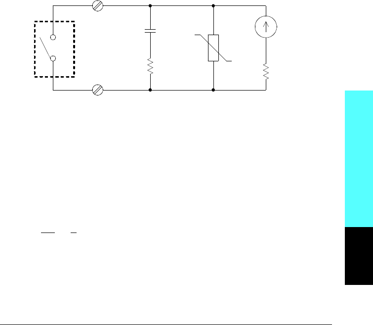
RC Protection Networks
When designing RC protection networks, the protection resistor Rp is
selected as a compromise between two resistance values. The minimum
value of R
p is determined by the maximum acceptable relay contact
current (I
max
). For the 34903A, the maximum allowable relay current
(I
max
) is 1A dc or ac rms. Thus, the minimum value for Rp is V/Io, where
V is the peak value of the supply voltage.
Rp =
V
I
max
=
V
2
Relay
Contact
C
p
R
p
Varistor
R
L
I
L
Module Reference
8
Chapter 8 Tutorial
Actuators and General-Purpose Switching
385


