


Current Measurements
Current measurements are allowed only on the 34901A module.
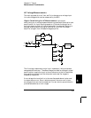
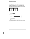
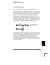
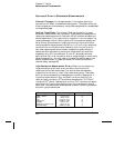
An ammeter senses the current flowing through its input connections –
approximating a short circuit between its input terminals. An ammeter
must be connected in series with the circuit or device being measured
such that current flows through both the meter and the test circuit.
A resistor, R
s
in the diagram below, is connected across the input
terminals such that a voltage drop proportional to the input current is
generated. The value of R
s
is selected as low as possible to minimize the
instrument’s burden voltage, or IR drop. This voltage drop is sensed by
the internal
DMM and scaled to the proper current value to complete
the measurement (see the discussion on the following page).
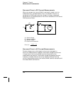
AC current measurements are very similar to dc current measurements.
The output of the current-to-voltage sensor is measured by an ac voltmeter.
The input terminals are direct coupled (ac+dc coupled) to the shunt so
that the internal
DMM maintains dc continuity in the test circuit.
Performing ac current measurements demands additional care.
The burden voltage (loading) varies with frequency and input inductance,
often causing unexpected behavior in the test circuit (see the discussion
on the following page).
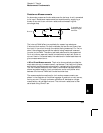
I
LO
On-Card
Fuse
S1
+/- Vdc to Input Amplifier and
Analog-to-Digital Converter
R
S
8
Chapter 8 Tutorial
Measurement Fundamentals
367