


Sources of Error in Multiplexing and Switching
Noise can be coupled inside a switch by the drive circuitry, by switch
thermal
EMFs, or by coupling among signal paths. Noise can also be
generated outside the network and conducted or coupled into the switch.
Although noise problems apply to the entire system, they can become
especially acute for switching. Switch networks contain a high
concentration of signals, which magnify the errors. Most problems with
electric noise can be traced to improper grounding and shielding (for more
information on grounding and shielding, see page 337).
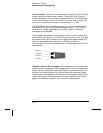
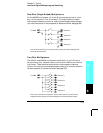
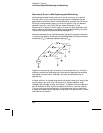
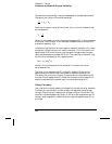
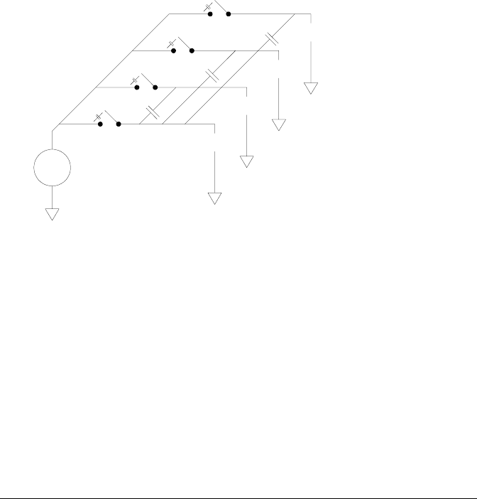
Noise can be capacitively coupled between physically adjacent channels
in a switching system. Noise can be coupled between the switch contacts
themselves (C
sw
) or between adjacent cabling (C
adj
).
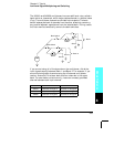
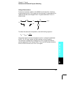
Capacitive noise coupling is a function of area and proximity. A simple
method to reduce the noise coupling is to physically separate the switches
and cables from each other. However, this may not be practical for all
applications.
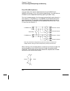
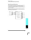
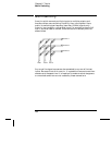
Another solution is to keep large amplitude signals and small amplitude
signals away from each other. Group similar signals together (high
voltages, low voltages, analog, and digital). If possible, use two separate
switch modules; one for high-level signals and one for low-level signals.
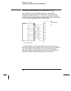
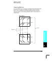
If you are using a single module for mixed-signal switching, leave one
unused, grounded channel between the groups. Also, ground any unused
channels on the module.
DMM
Source
Source
Source
Source
C
adj
C
sw
Chapter 8 Tutorial
Low-Level Signal Multiplexing and Switching
382