


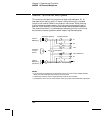
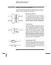
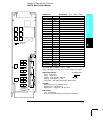
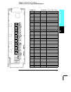

34907A Multifunction Module
This module combines two 8-bit ports of digital input/output, a 100 kHz
totalizer, and two
±12 analog outputs. For greater flexibility, you can read
digital inputs and the totalizer count during a scan.
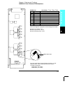
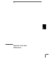
Digital Input/Output
The DIO consists of two 8-bit ports with
TTL-compatible inputs and output. The open-
drain outputs can sink up to 400 mA. From the
front panel, you can read data from only one 8-bit
input port at a time. From the remote interface,
you can read both ports simultaneously as a
16-bit word only if neither port is in the scan list.
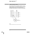
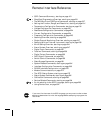
Totalize Input
The 26-bit totalizer can count pulses at a 100 kHz
rate. You can configure the totalizer to count on
the rising edge or falling edge of the input signal.
A
TTL high signal applied to the “G” terminal
enables counting and a low signal disables
counting. A
TTL low signal applied to the “G”
terminal enables counting and a high signal
disables counting. The totalizer only counts
when both terminals are enabled. Move the
Totalize Threshold jumper to the “
AC” position to
detect changes through 0 volts. Move the jumper
to the “
TTL” position (factory setting) to detect
changes through
TTL threshold levels.
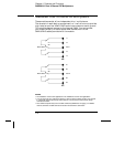
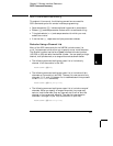
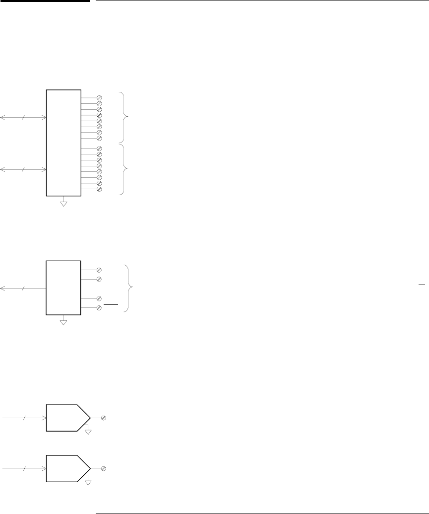
Analog Output (DAC)
The two analog outputs are capable of outputting
calibrated voltages between
±12 volts with 16 bits
of resolution. Each
DAC channel is capable of
10 mA maximum current. You must limit the
DAC output current to 40 mA total for all three
slots (six
DAC channels).
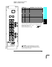
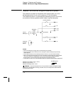
+IN
Gate
-IN
Gate
TOT
26 Bits
Channel 03
DAC 1
16
Channel 04
16
DAC 2
Channel 05
Bit 0
DIO
Bit 7
Bit 0
Bit 7
8
8
Port 1 (LSB)
Channel 01
Port 2 (MSB)
Channel 02
Chapter 4 Features and Functions
34907A Multifunction Module
174