


System Cabling and Connections
This section describes methods to reduce measurement errors that can
be introduced by your system cabling. Many system cabling errors can
be reduced or eliminated by selecting the proper cable and grounding
scheme for your system.
Cable Specifications
A wide variety of general-purpose and custom cables are available.
The following factors influence the type of cable that you choose.
• Signal Requirements – such as voltage, frequency, accuracy, and
measurement speed.
• Interconnection Requirements – such as wire sizes, cable lengths,
and cable routing.
• Maintenance Requirements – such as intermediate connectors,
cable terminations, strain relief, cable lengths, and cable routing.
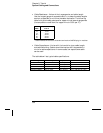
Cables are specified in a variety of ways. Be sure to check the following
specifications for the cable type you intend to use (continued on the
following page).
• Nominal Impedance (insulation resistance) – Varies with the
frequency of the input signal. Check for
HI-to-LO, channel-to-
channel, and
HI- or LO-to-shield. High frequency RF applications
have exact requirements for cable impedance.
• Dielectric Withstand Voltage – Must be high enough for your application.
WARNING
To prevent electrical shock or equipment damage, insulate all channels to
the highest potential in the system. It is recommended that you use wire
with 600 V rated insulation.
8
Chapter 8 Tutorial
System Cabling and Connections
335