


Totalizer Operations
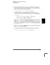
The multifunction module has a 26-bit totalizer which can count TTL
pulses at a 100 kHz rate. You can manually read the totalizer count
or you can configure a scan to read the count.
• The totalizer channel is numbered “s03”, where s represents the
slot number.
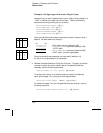
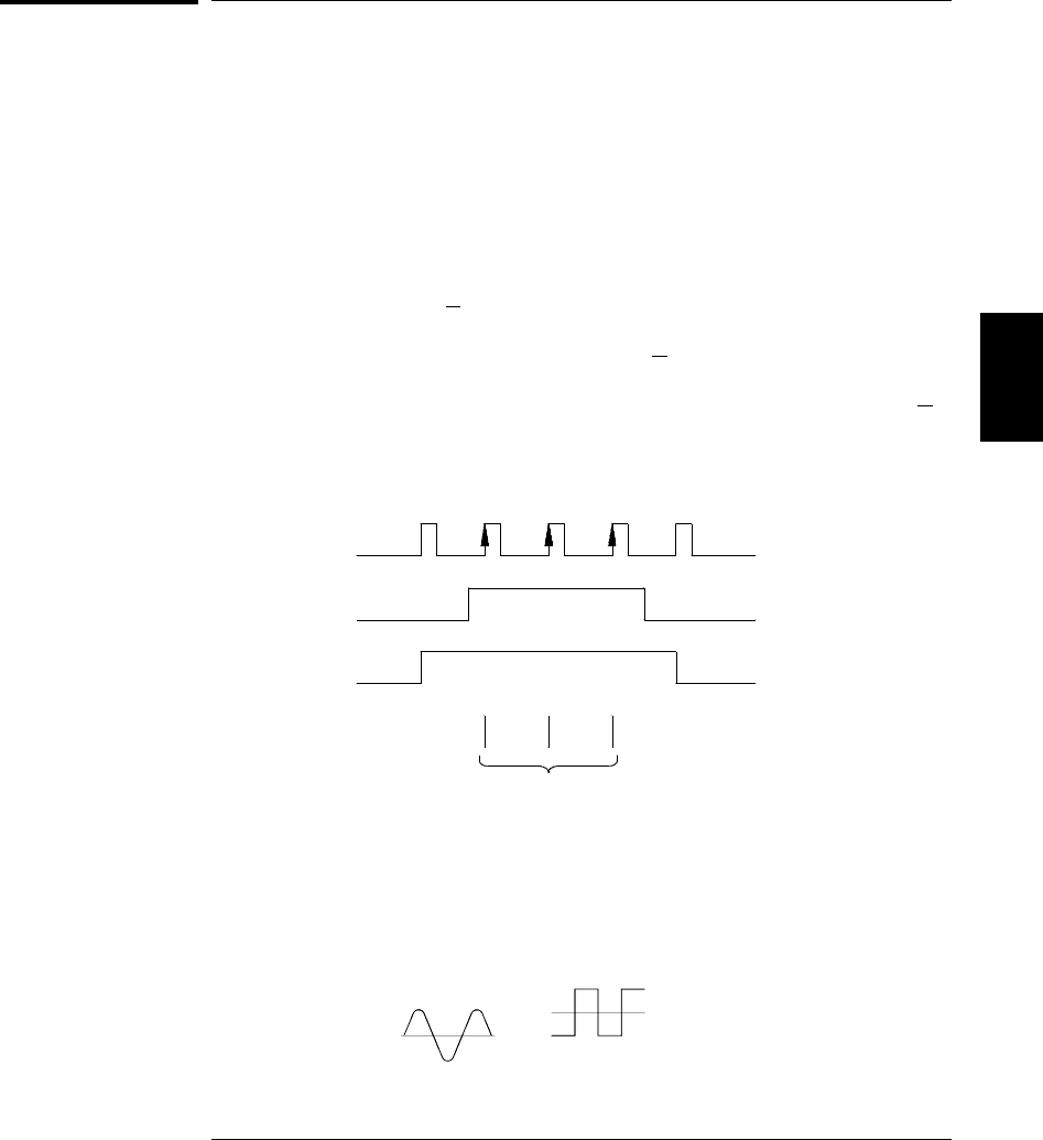
• You can configure the instrument to count on the rising edge or
falling edge of the input signal.
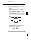
• You can control when the totalizer actually records counts by providing
a gate signal (
G and G terminals on the module). A TTL high signal
applied to the “
G” terminal enables counting and a low signal disables
counting. A
TTL low signal applied to the “G” terminal enables counting
and a high signal disables counting. The totalizer only counts when
both terminals are enabled. You can use either the
G terminal, the G
terminal, or both. When a gate is not connected, the gate terminal
floats to the enabled state, effectively creating a “gate always” condition.
• Using the hardware jumper labeled “Totalize Threshold” on the
module, you can control the threshold at which an edge is detected.
Move the jumper to the “
AC” position to detect changes through
0 volts. Move the jumper to the “
TTL” position (factory setting)
to detect changes through
TTL threshold levels.
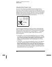
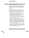
Input Signal
(Rising Edge)
Add to Total
Totalizer Input
Gate Signal
(High True)
2.5 V Threshold (TTL)
0 V Threshold (AC)
4
Chapter 4 Features and Functions
Totalizer Operations
135