


The 34970A Data Acquisition / Switch Unit
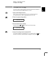
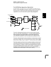
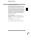
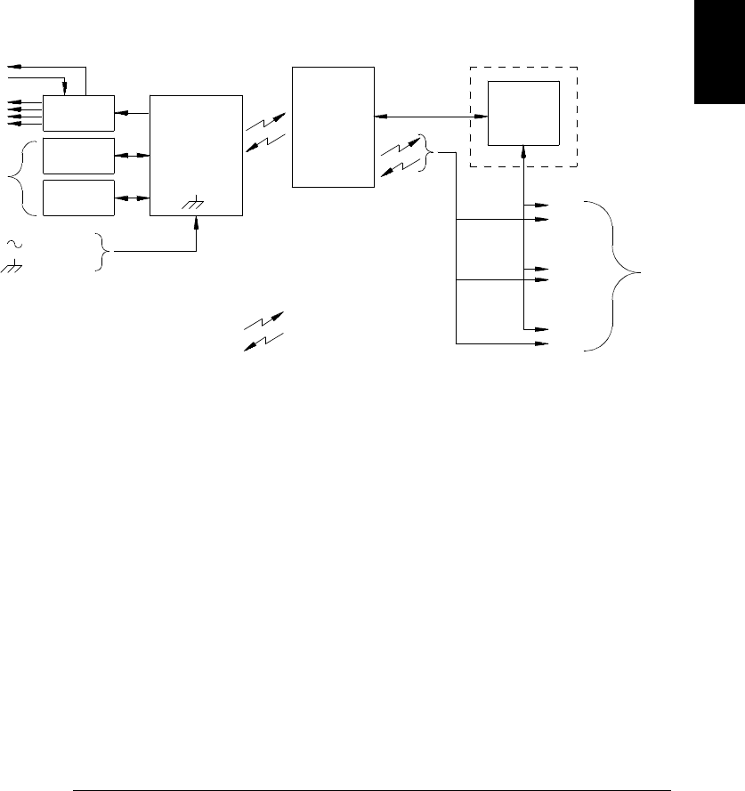
As shown below, the logic circuitry for the 34970A is divided into two
sections: earth-referenced and floating. These two sections are isolated
from each other in order to maintain measurement accuracy and
repeatability (for more information on ground loops, see page 341).
The earth-referenced and floating circuitry communicate with each
other via an optically-isolated data link. The earth-referenced section
communicates with the floating section to provide
PC connectivity.
The instrument is shipped with both an
GPIB (IEEE-488) interface
and an RS-232 interface. Only one interface can be enabled at a time.
The earth-referenced section also provides four hardware alarm outputs
and external trigger lines. You can use the alarm output lines to trigger
external alarm lights, sirens, or send a
TTL pulse to your control system.
The floating section contains the main system processor and controls all
of the basic functionality of the instrument. This is where the instrument
communicates with the plug-in modules, scans the keyboard, controls the
front-panel display, and controls the internal
DMM. The floating section
also performs Mx+B scaling, monitors alarm conditions, converts
transducer measurements to engineering units, time stamps scanned
measurements, and stores data in non-volatile memory.
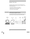
To Computer
AC Power
Alarms
GPIB
RS-232
Earth
Referenced
Logic
Floating
Logic
Internal
DMM
Digital
Bus
Analog Bus
Plug-In
Slots
100
200
300
External Trigger
Control
Optional
= Optical Isolators
OUT
IN
3
Chapter 3 System Overview
Data Acquisition System Overview
53