


DC Voltage Measurements
To make a useful dc meter, a “front-end” is required to condition the
input before the analog-to-digital conversion. Signal conditioning
increases the input resistance, amplifies small signals, and attenuates
large signals to produce a selection of measuring ranges.
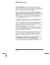
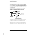
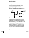
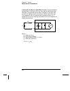
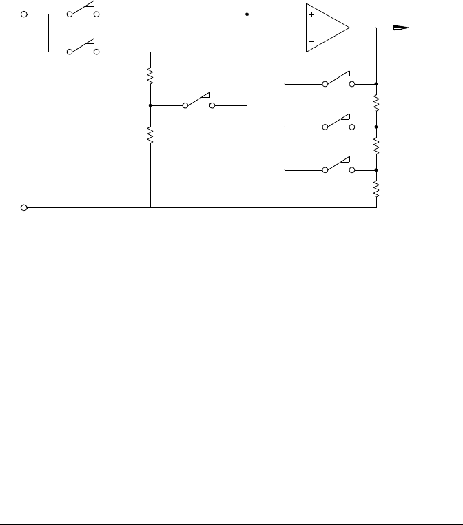
Signal Conditioning for DC Measurements Input signal
conditioning for dc voltage measurements includes both amplification
and attenuation. A simplified input to the internal
DMM is shown below.
For input voltages less than 12 Vdc, the Low V switch is closed and
applies the input signal directly to the input amplifier. For higher
voltages, the High V switch is closed and the signal is attenuated 100:1
before being applied to the input amplifier. The input amplifier gain is
set to one of three values (x1, x10, or x100) to yield a signal in the range
of
±12 Vdc for the analog-to-digital converter.
For the lower voltage ranges, the internal
DMM’s input resistance is
essentially that of the input amplifier. The input amplifier uses a
low-bias current (less than 50 pA)
FET input stage yielding an input
resistance greater than 10 G
Ω. On the 100V and 300V input ranges,
the input resistance is determined by the total resistance of the 100:1
divider. You can also set the input resistance to 10 M
Ω by continuously
closing the High V switch (for more information on dc input resistance,
see page 113).
HI
LO
Low V
High V
100:1
X1
X10
X100
+/- 12 Vdc to
Analog-to-Digital
Converter
Ranging
Chapter 8 Tutorial
Measurement Fundamentals
354