


Digital Output Operations
The multifunction module (34907A) has two non-isolated 8-bit
input/output ports which you can use for outputting digital patterns.
• The digital output channels are numbered “s01” (lower byte)
and “s02” (upper byte), where s represents the slot number.
• You cannot configure a port for output operations if that port is
already configured to be part of the scan list (digital input).
• From the front panel, you can write to one 8-bit output port at a time.
From the remote interface, you can write to both ports simultaneously.
• From the front-panel only, you can specify whether you want to use
binary or decimal format. Once you have selected the number base,
it is used for all input or output operations on the same port.
• A Factory Reset (*RST command), Instrument Preset (SYSTem:PRESet
command), and Card Reset (SYSTem:CPON command) from the
remote interface will reconfigure both ports as input ports.
Note that a from the front panel resets only the port currently
selected (both ports are not reset).
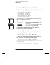
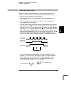
• Front-Panel Operation: After selecting the output port, press
to edit the bit pattern or decimal value (the least significant bit is on
the right). Press again to output the bit pattern. To cancel an
output operation in progress, wait for the display to time out.
From the front-panel only, you can specify whether you want to use
binary or decimal format.
USE DECIMAL , USE BINARY
• Remote Interface Operation: From the remote interface, you can
output an 8-bit byte to one port or a 16-bit word to both ports
simultaneously using the following commands. You must specify a
decimal value (binary data is not accepted). If you are going to read
both ports simultaneously, you must send the command to port 01.
SOUR:DIG:DATA:BYTE 10 ,(
@302) Write to port 02
SOUR:DIG:DATA:WORD 10327 ,(
@301) Write to both ports
Chapter 4 Features and Functions
Digital Output Operations
138