


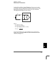
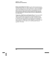
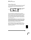


Low-Level AC Measurement Errors When measuring ac voltages
less than 100 mV, be aware that these measurements are especially
susceptible to errors introduced by extraneous noise sources. An exposed
test lead will act as an antenna and the internal
DMM will measure the
signals received. The entire measurement path, including the power
line, act as a loop antenna. Circulating currents in the loop will create
error voltages across any impedances in series with the instrument’s
input. For this reason, you should apply low-level ac voltages to the
instrument through shielded cables. You should also connect the shield
to the input
LO terminal.
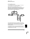
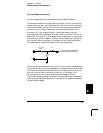
Be sure to minimize the area of any ground loops that cannot be
avoided. A high-impedance source is more susceptible to noise pickup
than a low-impedance source. You can reduce the high-frequency
impedance of a source by placing a capacitor in parallel with the
instrument’s input terminals. You may have to experiment to determine
the correct capacitance value for your application.
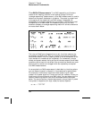
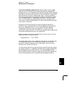
Most extraneous noise is not correlated with the input signal. You can
determine the error as shown below.
Voltage Measured = √ V
in
2
+ Noise
2
Correlated noise, while rare, is especially detrimental. Correlated noise
will always add directly to the input signal. Measuring a low-level
signal with the same frequency as the local power line is a common
situation that is prone to this error.
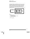
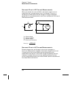
You should use caution when switching high-level and low-level signals
on the same module. It is possible that high-level charged voltages may
be discharged onto a low-level channel. It is recommended that you
either use two different modules or separate the high-level signals from
the low-level signals with an unused channel connected to ground.
8
Chapter 8 Tutorial
Measurement Fundamentals
365