


• Alarms are logged in the alarm queue only when a reading crosses a
limit, not while it remains outside the limit and not when it returns
to within limits.
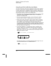
• Four TTL alarm outputs are available on the rear-panel Alarms
connector. You can use these hardware outputs to trigger external
alarm lights, sirens, or send a
TTL pulse to your control system.
You can also initiate a scan sweep (no external wiring required) when
an alarm event is logged on a channel. For complete details, refer to
“Using the Alarm Output Lines” on page 128.
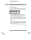
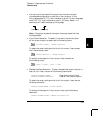
• The following table shows the different combinations of front-panel
annunciators that may appear while using alarms.
• In addition to being stored in reading memory, alarms are also
recorded in their own
SCPI status system. You can configure the
instrument to use the status system to generate a Service Request
(
SRQ) when alarms are generated. See “The SCPI Status System,”
starting on page 275 for more information.
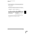
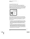
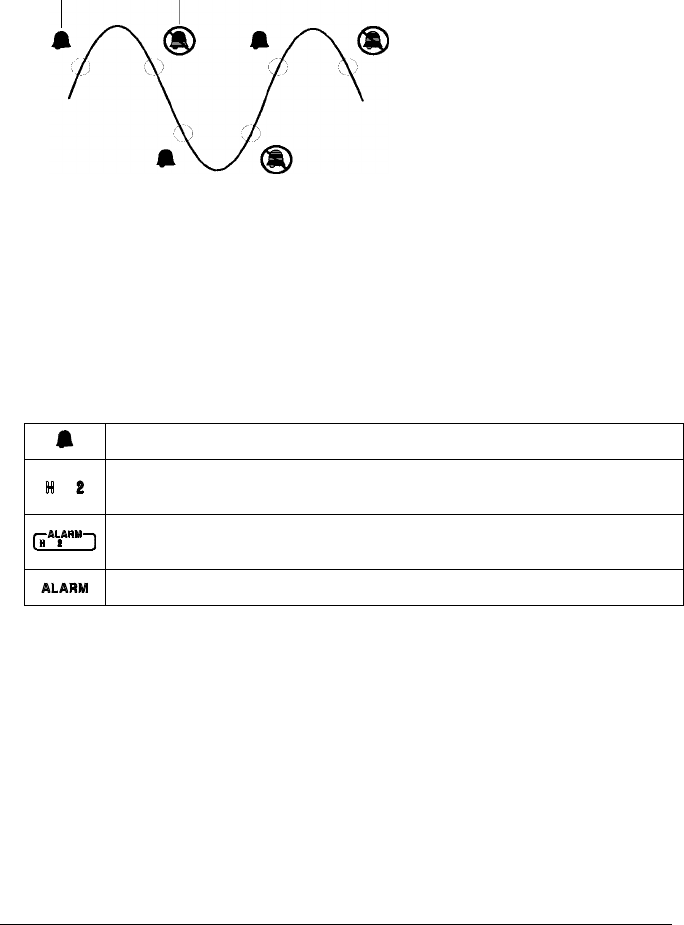
• The default values for the upper and lower alarm limits are “0”.
The lower limit must always be less than or equal to the upper limit,
even if you are using only one of the limits.
Upper Limit
Lower Limit
Alarm Event
No Alarm
An alarm is enabled on the displayed channel.
The indicated HI or LO limit is being configured on the indicated alarm
(shown while in the Alarm menu).
An alarm has occurred on one or more channels. The behavior of the
alarm output lines tracks the alarm annunciators on the front panel.
The alarm output lines have been cleared but alarms remain in the queue.
Chapter 4 Features and Functions
Alarm Limits
124