Alarm Output Commands
Four TTL alarm outputs are available on the rear-panel Alarms
connector. You can use these hardware outputs to trigger external
alarm lights, sirens, or send a
TTL pulse to your control system.
Each alarm output line represents the logical “
OR” of all channels
assigned to that alarm number (an alarm on any of the associated
channels will pulse the line).
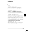
OUTPut
:ALARm:MODE {LATCh|TRACk}
:ALARm:MODE?
Select the configuration of the four alarm output lines (the configuration
applies to all four alarm output lines). In the “
LATCh” mode (default),
the corresponding output line is latched true when the first alarm
occurs and remains asserted until you clear it by initiating a new scan or
cycling power. In the “
TRACk” mode, the corresponding output line is
asserted only when a reading crosses a limit and remains outside the limit.
When a reading returns to within limits, the output line is automatically
cleared. The :MODE? query returns the alarm output configuration.
Returns “
LATC” or “TRAC”.
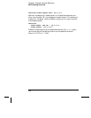
OUTPut
:ALARm:SLOPe {NEGative|POSitive}
:ALARm:SLOPe?
Select the slope of the pulse from the alarm outputs (the selected
configuration is used for all four outputs). If you select NEG (default),
0V (
TTL low) indicates an alarm. If you select POS, +5V (TTL high)
indicates an alarm. The :POL? query returns the alarm output
configuration. Returns “
NEG” or “POS”. Note that changing the slope of
the output lines may cause the lines to change state.
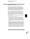
OUTPut
:ALARm{1|2|3|4}:CLEar
:ALARm:CLEar:ALL
Clear the specified alarm output lines. Send :CLEAR:ALL to clear all
four alarm output lines. You can manually clear the output lines at any
time (even during a scan) and the alarm data in memory is not cleared
(however, data is cleared when you initiate a new scan). The alarm
outputs are also cleared when you initiate a new scan.
Chapter 5 Remote Interface Reference
Alarm System Overview
252


