Module Reference
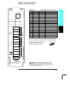
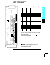
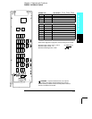
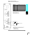
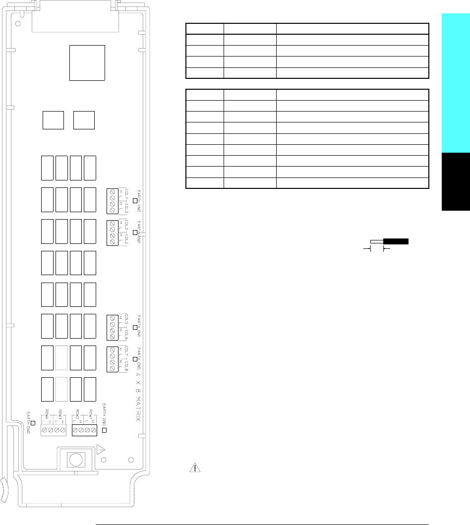
WIRING LOG Slot Number: ❒ 100 ❒ 200 ❒ 300
Row Name Comments
1
2
3
4
Column Name Comments
1
2
3
4
5
6
7
8
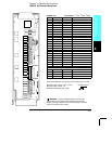
Example: Channel 32 represents Row 3 and Column 2.
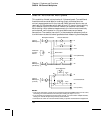
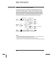
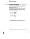
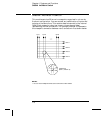
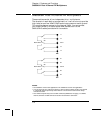
Refer to the diagrams on page 20 to connect wiring to the module.
Maximum Input Voltage: 300 V (CAT I)
Maximum Input Current: 1 A
Maximum Switching Power: 50 W
WARNING: To prevent electrical shock, use only wire
that is rated for the highest voltage applied to any channel.
Before removing a module cover, turn off all power to external
devices connected to the module.
6 mm
20 AWG Typical
4
Chapter 4 Features and Functions
34904A 4x8 Matrix Switch
171


