


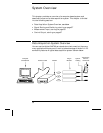
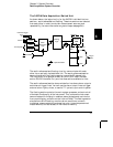


Signal Routing and Switching
The switching capabilities of the plug-in modules available with the
34970A provide test system flexibility and expandability. You can use
the switching plug-in modules to route signals to and from your test
system or multiplex signals to the internal
DMM or external instruments.
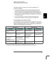
Relays are electromechanical devices which are subject to wear-out
failure modes. The life of a relay, or the number of actual operations
before failure, is dependent upon how it is used – applied load, switching
frequency, and environment. The 34970A Relay Maintenance System
automatically counts the cycles of each relay in the instrument and
stores the total count in non-volatile memory on each switch module.
Use this feature to track relay failures and to predict system maintenance
requirements. For more information on using this feature, refer to
“Relay Cycle Count” on page 147.
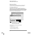
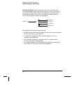
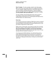
Switching Topologies
Several switching plug-in modules are available with different
topologies for various applications. The following switching topologies
are available:
• Multiplexer (34901A, 34902A, 34905A, 34906A, 34908A)
• Matrix (34904A)
• Form C – Single Pole, Double Throw (34903A)
The following sections describe each of these switching topologies.
3
Chapter 3 System Overview
Signal Routing and Switching
57