


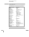
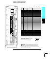
Factory Reset State
The table below shows the state of the instrument after a FACTORY RESET
from the Sto/Rcl menu or *RST command from the remote interface.
Measurement Configuration
Function
Range
Resolution
Integration Time
Input Resistance
Channel Delay
Totalizer Reset Mode
Totalizer Edge Detect
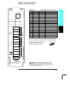
Scanning Operations
Scan List
Reading Memory
Min, Max, and Average
Scan Interval Source
Scan Interval
Scan Count
Scan Reading Format
Monitor in Progress
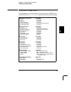
Mx+B Scaling
Gain Factor (“M”)
Scale Factor (“B”)
Scale Label
Alarm Limits
Alarm Queue
Alarm State
HI and LO Alarm Limits
Alarm Output
Alarm Output Configuration
Alarm Output State
Alarm Output Slope
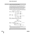
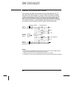
Module Hardware
34901A, 34902A, 34908A
34903A, 34904A
34905A, 34906A
34907A
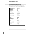
System-Related Operations
Display State
Error Queue
Stored States
Factory Reset State
DC Volts
Autorange
5
1
⁄
2
digits
1 PLC
10 M
Ω (fixed for all DCV ranges)
Automatic Delay
Count Not Reset When Read
Rising Edge
Factory Reset State
Empty
All Readings are Cleared
All Statistical Data is Cleared
Immediate
Front Panel = 10 Seconds
Remote = Immediate
Front Panel = Continuous
Remote = 1 Scan Sweep
Reading Only (No Units, Channel, Time)
Stopped
Factory Reset State
1
0
Vdc
Factory Reset State
Not Cleared
Off
0
Alarm 1
Latched Mode
Output Lines are Cleared
Fail = Low
Factory Reset State
Reset: All Channels Open
Reset: All Channels Open
Reset: Channels s11 and s21 Selected
Reset: Both DIO Ports = Input, Count = 0,
Both DACs = 0 Vdc
Factory Reset State
On
Errors Not Cleared
No Change
Chapter 4 Features and Functions
Factory Reset State
160