


Digital Output
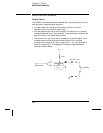
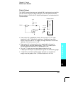
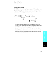
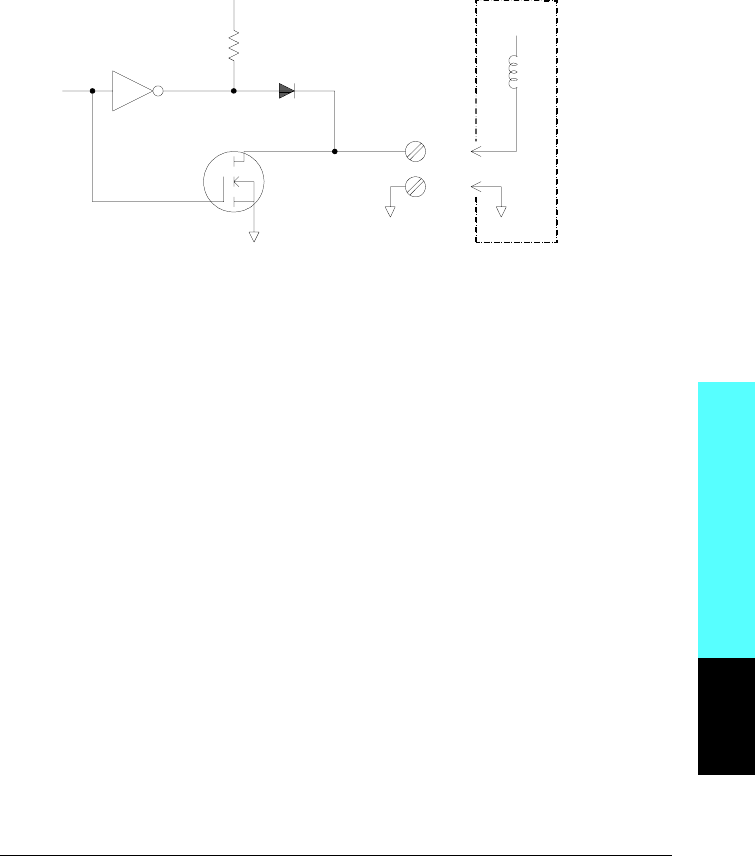
The 34907A module has two non-isolated 8-bit input/output ports which
you can use for outputting digital patterns. You can combine the two
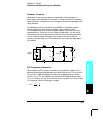
ports to output a 16-bit word. A simplified diagram of a single output bit
is shown below.
• Each output bit is capable of directly driving up to 10 TTL loads
(less than 1 mA). The buffer for each port is used to drive a high
output from the internal +5V supply through the diode. The drive is
rated at +2.4V minimum at 1 mA.
• Each output bit is also an active sink, capable of sinking up to
400 mA from an external power supply. The
FET is used to sink
currents and has a nominal “on” resistance of 0.2
Ω.
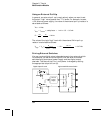
• For non-TTL logic you must provide an external pull-up.
A description of the pull-up calculation is given on the following page.
• If used with an external power supply and pull-up, the external
supply must be greater than +5 Vdc and less than +42 Vdc.
Output
I/O Line
(1 of 16)
+5 V
0.2
Ω
10 kΩ
External Circuit
+V
Module Reference
8
Chapter 8 Tutorial
Multifunction Module
393