


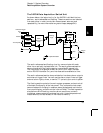

Transducers and Sensors
Transducers and sensors convert a physical quantity into an electrical
quantity. The electrical quantity is measured and the result is then
converted to engineering units. For example, when measuring a
thermocouple, the instrument measures a dc voltage and mathematically
converts it to a corresponding temperature in
°C, °F, or K.
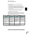
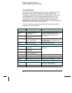
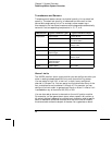
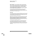
Measurement Typical Transducer Types Typical Transducer Output
Temperature Thermocouple 0 mV to 80 mV
RTD 2-wire or 4-wire resistance
from 5
Ω to 500Ω
Thermistor 2-wire resistance from
10
Ω to 1 MΩ
Pressure Solid State ±10 Vdc
Flow Rotary Type
Thermal Type
4 mA to 20 mA
Strain Resistive Elements 4-wire resistance from
10
Ω to 10 kΩ
Events Limit Switches
Optical Counters
Rotary Encoder
0V or 5V Pulse Train
Digital System Status TTL Levels
Alarm Limits
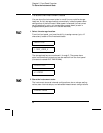
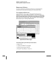
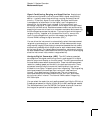
The 34970A has four alarm outputs which you can configure to alert you
when a reading exceeds specified limits on a channel during a scan.
You can assign a high limit, a low limit, or both to any configured
channel in the scan list. You can assign multiple channels to any of the
four available alarms (numbered 1 through 4). For example, you can
configure the instrument to generate an alarm on Alarm 1 when a limit
is exceeded on any of channels 103, 205, or 320.
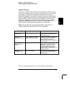
You can also assign alarms to channels on the multifunction module.
For example, you can generate an alarm when a specific bit pattern or
bit pattern change is detected on a digital input channel or when a specific
count is reached on a totalizer channel. With the multifunction module,
the channels do not have to be part of the scan list to generate an alarm.
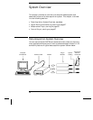
Chapter 3 System Overview
Data Acquisition System Overview
56