


Using Alarms With the Multifunction Module
You can configure the instrument to generate an alarm when a specific
bit pattern or bit pattern change is detected on a digital input channel
or when a specific count is reached on a totalizer channel. These channels
do not have to be part of the scan list to generate an alarm. Alarms are
evaluated continuously as soon as you enable them.
• The digital input channels are numbered “s01” (lower byte) and “s02”
(upper byte), where s represents the slot number. The totalizer
channel is numbered “s03”.
• Alarms are evaluated continuously on the multifunction module,
but alarm data is stored in reading memory only during a scan.
• Each time you start a new scan, the instrument clears all readings
(including alarm data) stored in reading memory from the previous
scan. However, alarm data stored in the alarm queue from the
multifunction module is not cleared. Therefore, although the contents
of reading memory are always from the most recent scan, the alarm
queue may contain data that occurred during previous scans or while
the instrument was not scanning.
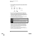
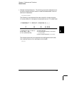
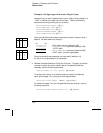
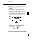
• Front-Panel Operation: To configure an alarm on a digital input
channel, choose from the following items and then set the desired
bit pattern. Set each bit to “0”, “1”, or “X” (don’t care). You can either
specify that an alarm will occur when certain bits change or when a
specific 8-bit pattern is read.
NOT PATTERN , PATTERN MATCH
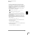
To configure an alarm on a totalizer channel, select a high limit and
then set the desired count for the selected alarm.
HI ALARM ONLY
;%,1
Bit 7 Bit 0
Chapter 4 Features and Functions
Alarm Limits
130