


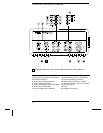
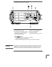
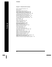

The Rear Panel at a Glance
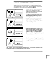
WARNING
For protection from electrical shock, the power cord ground must not be
defeated. If only a two-contact electrical outlet is available, connect the
instrument’s chassis ground screw (see above) to a good earth ground.
1 Slot Identifier (100, 200, 300)
2 Ext Trig Input / Alarm Outputs / Channel
Advance Input / Channel Closed Output
(for pinouts, see pages 83 and 128)
3 RS-232 Interface Connector
4 Power-Line Fuse-Holder Assembly
5 Power-Line Voltage Setting
6 Chassis Ground Screw
7 GP-IB (IEEE-488) Interface Connector
Use the Menu to:
• Select the GP-IB or RS-232 interface (see chapter 2).
• Set the GP-IB address (see chapter 2).
• Set the RS-232 baud rate, parity, and flow control mode (see chapter 2).
5