


F-44 F-44
INPUT POWER AND WIRING HARNESS TEST
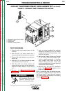
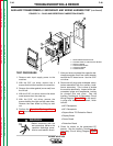
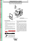
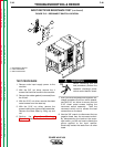
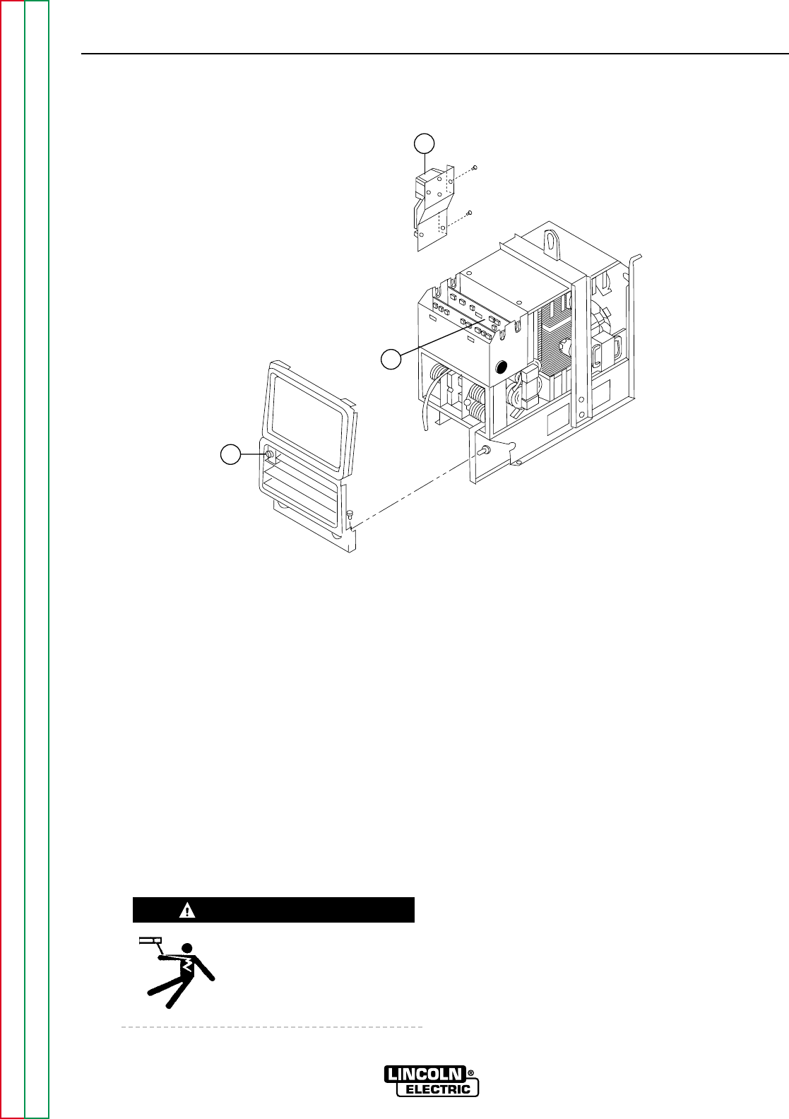
FIGURE F.13 - INPUT POWER INSPECTION POINTS
1
2
3
TROUBLESHOOTING & REPAIR
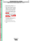
TEST PROCEDURE
1. Remove main input supply power to the
machine.
2. With the 3/8" nut driver, remove the 4
screws that hold the handle to the machine.
3. Remove the rubber gasket (cover seal) from
the lift bail.
4. With the 5/16" nut driver, remove the sheet
metal screws from the case top.
5. With the 5/16" nut driver, remove the
screws holding the right and left case sides.
Remove the case sides by lifting up and
out.
6. Perform the Capacitor Discharge Pro-
cedure described earlier in this section of
the manual.
Before continuing with the
test procedure, perform the
capacitor discharge proce-
dure to avoid electric shock.
7. After you have completed the capacitor dis-
charge procedure for all four switch boards,
remove the PC board cover. Use the 5/16"
nut driver.
8. Manually check the power switch (S1) for
proper operation by turning it back and
forth. At the back of the front panel where
the switch is mounted, make a visual
inspection. Be sure the input and output
leads are not shorted together. Make sure
the switch contacts are not fused together
or shorted to another phase. (Because of
the high input voltage involved, you should
be able to see physical evidence if any of
these problems exist.) Remove the tape
covering the switch and check the switch
with an ohmmeter. High resistance should
be present.
POWER WAVE 450
Return to Section TOC Return to Section TOC Return to Section TOC Return to Section TOC
Return to Master TOC Return to Master TOC Return to Master TOC Return to Master TOC
WARNING
1. POWER SWITCH (S1)
2. MAIN CONTACTOR INPUT LEADS (TOP)
3. PROTECTION BOARD