


Return to Section TOC Return to Section TOC Return to Section TOC Return to Section TOC
Return to Master TOC Return to Master TOC Return to Master TOC Return to Master TOC
POWER WAVE 450
F-24 F-24
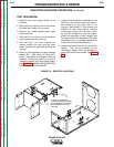
CAPACITOR DISCHARGE PROCEDURE (continued)
TROUBLESHOOTING & REPAIR
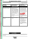
TEST PROCEDURE
1. Remove main input supply power to the
machine.
2. With the 3/8" nut driver, remove the screws
that hold the handle to the machine.
3. Remove the rubber gasket (cover seal)
from the lift bail.
4. With the 5/16" nut driver, remove the sheet
metal screws from the case top.
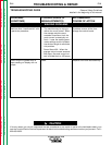
5. With the 5/16" nut driver, remove the
screws holding the right and left case
sides. Remove the case sides by lifting up
and out.
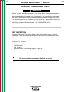
6. Obtain a high resistance and high wattage
resistor (25 - 1000 ohms, 25 watts mini-
mum). This resistor is not supplied with the
machine. Secure this resistor to a piece of
insulating material such as a glastic board.
See Figure F.4. NEVER USE A SHORTING
STRAP FOR THIS PROCEDURE.
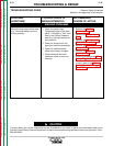
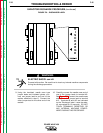
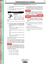
7. Locate the two sets of two resistors on the
left side of the machine and three sets of
two resistors on the right side of the
machine. See Figure F.2. Do not touch the
resistors or any other internal machine
component. Using a DC voltmeter, check
for any DC voltage that may be present
across the terminals of each resistor and
from each resistor to case ground (20 mea-
surements in all). If a voltage is present, be
careful not to touch these resistors.
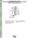
8. Locate terminals #9 and #12 on the switch
boards. They can be identified by the
“Discharge” labels, which are located on
each of the four switch boards. See Figure
F.3.
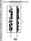
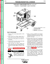
FIGURE F.2 – RESISTOR LOCATIONS
5 PAIRS OF RESISTORS
CHECK VOLTAGES BETWEEN
EACH TERMINAL AND FROM
EACH RESISTOR TO CASE
GROUND