


Return to Section TOC Return to Section TOC Return to Section TOC Return to Section TOC
Return to Master TOC Return to Master TOC Return to Master TOC Return to Master TOC
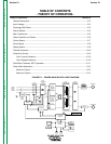
THEORY OF OPERATION
E-9 E-9
POWER WAVE 450
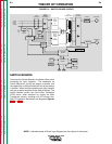
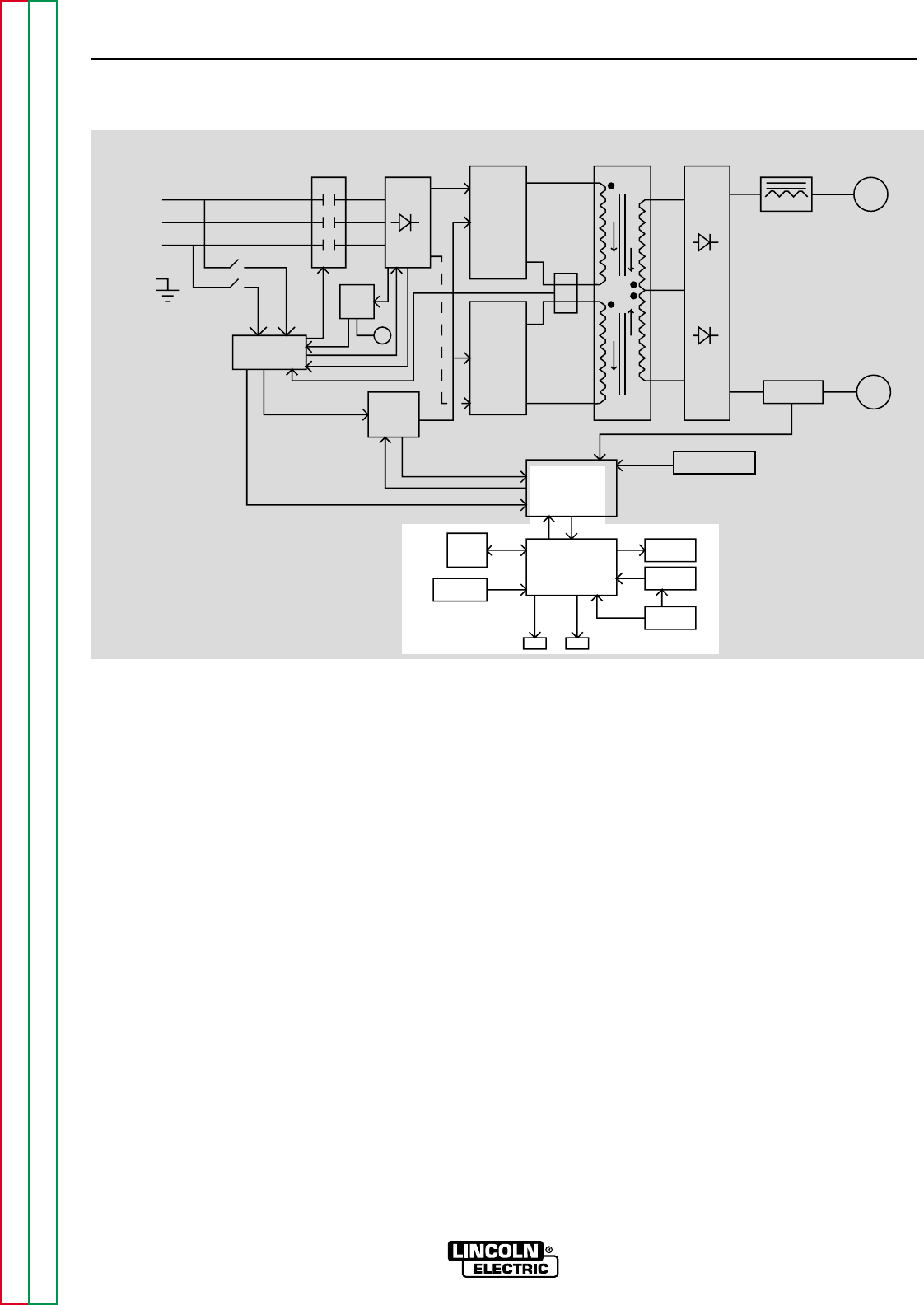
DISPLAY BOARD
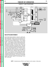
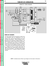
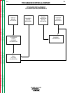
The Display Board allows the operator to select from
the procedures that are programmed into the
machine, and it lets the Control Board know which
procedure was selected. These procedures are pro-
grammed into the machine’s software package. The
Display Board is used to communicate with the oper-
ator. It determines what Overlay is installed in the
machine and which buttons are active on the keypad.
It also controls the LCD display, the lights on the front
of the machine, the Piezo Buzzer and the water cool-
er. Through the use of a current serial loop, the
Display Board and Control Board communicate (or
talk) to the wire feeder(s). The Display Board can also
communicate with a computer through the RS232
interface.
FIGURE E.9 – DISPLAY BOARD
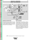
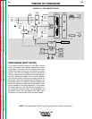
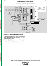
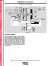
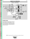
NOTE: Unshaded areas of Block Logic Diagram are the subject of discussion.
CONTROL
BOARD
DISPLAY
BOARD
PROTECTION
BOARD
AUX.
TRANS
POWER
BOARD
CT
CONTACTOR
INPUT
INPUT
RECTIFIER
AND
RECONNECT
SWITCH
BOARD
FET
ASSEMBLY
SWITCH
BOARD
FET
ASSEMBLY
MAIN
TRAMSFORMER
OUTPUT
RECTIFIER
SHUNT
CHOKE POSITIVE
NEGATIVE
SNUBBER AND
LEADS
SENSE
LCD
DISPLAY
KEYPAD
OVERLAY
WATER
COOLER
PC
INTERFACE
INPUT
LINE
SWITCH
FAN
WF1 WF2
THREE
PHASE
INPUT
POWER
LEFT
RIGHT