


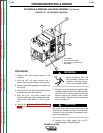
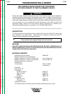
SETUP THE POWER WAVE FOR
PRETEST
1. Turn the input power switch to the OFF
position.
2. Unplug P73. See wiring diagram.
3. Install the L9660-255 Calibration & Test over-
lay into the Power Wave.
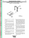
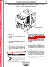
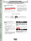
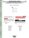
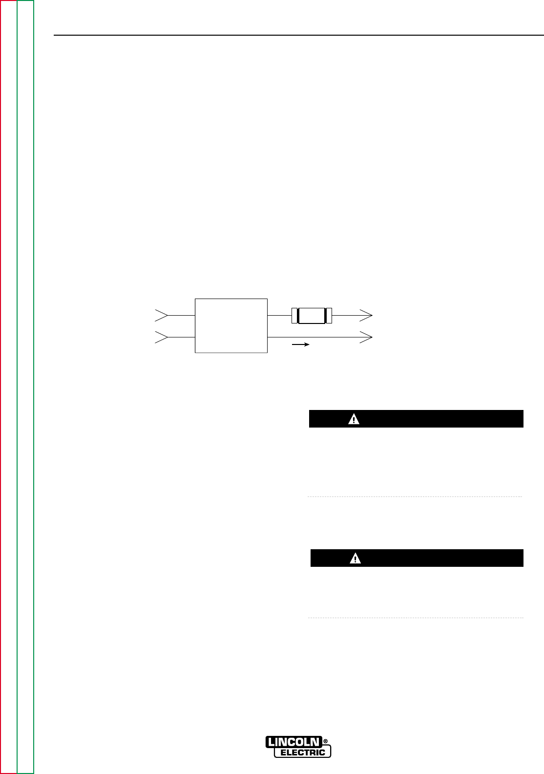
4. Construct an isolated variable AC supply
circuit as shown in Figure F.76 using the
following equipment:
Isolation transformer 115vac @ 3 amps.
5 amp Variac.
5 amp Fuse.
5. Connect the variable AC supply leads to the
Power Wave input rectifier terminals AC1 (T1),
and AC3 (T3). See Figure F.76. Make certain
the variac is at zero volts output.
ALL AC SUPPLIES MUST BE ELECTRICALLY
ISOLATED (Isolation transformers). THE
PRINTED CIRCUIT BOARDS WILL BE DAM-
AGED IF THE AC SUPPLIES ARE NOT
ISOLATED.
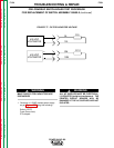
6. Monitor the filter capacitor voltage as per
Figure F.77.
WARNING: ALL METERS AND OSCILLO-
SCOPES MUST BE ELECTRICALLY ISOLAT-
ED (Isolation transformers).
TROUBLESHOOTING & REPAIR
F-200 F-200
POWER WAVE 450
Return to Section TOC Return to Section TOC Return to Section TOC Return to Section TOC
Return to Master TOC Return to Master TOC Return to Master TOC Return to Master TOC
PRE-POWERUP SWITCH BOARD TEST PROCEDURE
FOR REPLACEMENT OF SWITCH ASSEMBLY G2402-2 (continued)
FILTER CAPACITOR POLARITY
TEST
1. Perform this procedure with the input power
removed. Perform the CAPACITOR DIS-
CHARGE Procedure to remove any charge
from the input filter capacitors.
2. Configure the machine for 230VAC opera-
tion.
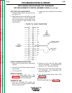
3. Attach the ohmmeter (set to 1 K ohm range)
across one of the 7.5K ohm bleeder resistors
(R9 or R10). See wiring diagram.
4. Attach the positive meter probe to wire #9
and the negative meter probe to lead #12.
The resistance should slowly increase to a
value between 3K ohms and 3.5K ohms.
5. Repeat the procedure for the other bleeder
(7.5K ohm) resistor.
ISOLATED
115 VAC
INPUT RECTIFIER: AC1 (T1)
INPUT RECTIFIER: AC3 (T3)
0
115 VAC
PRIMARY
VOLTAGE
VARIABLE
5A
FUSE
WARNING
FIGURE F.76 - AC SUPPLY LEADS
WARNING